6 7
OVERVIEWINSTALLATION
PLANNING
SPEAKER LOCATION &
INSTALLATION
SET UP &
INTEGRATION
INSTALLING OPTIONAL
EQUIPMENT
TROUBLESHOOTING
SNAP THE T-BAR INTO PLACE TO CREATE A
’ X ’ OPENING AND A ’ X ’ OPENING
NEW T-BAR
EXISTING TILE GRID
/ TILE
TCQ
SPEAKER LOCATION & INSTALLATION
TOOLS AND EQUIPMENT TO INSTALL THE SPEAKERS OUTLINED IN THIS MANUAL
Locate the specific speaker(s) that were ordered with the system and then follow the installation instructions for the model of speaker outlined in this section of the manual.
• Straight edge
• Utility knife or drywall saw
• Screwdriver, standard and phillips
• Screwdriver, small jewelers type, 1/8” wide tip
• Drill driver and bits/drills
• Drill driver and bits/drills
• Marker or pencil
• Wire cutters
• Wire strippers
• Wire ties
TCQ Speaker Installation
SYSTEM COMPONENTS AND UNPACKING
• (1) Ceiling grid T-bar (US & Canada use)
• (1) 50 (15m) plenum rated speaker wire (If ordered)
• (1) 20 (6m) coil safety wire
• (4) Self drilling screws (outside U.S. and Canada)
NOTE: Wiring should follow the class 2 wiring methods as outlined in the National Electric Code.
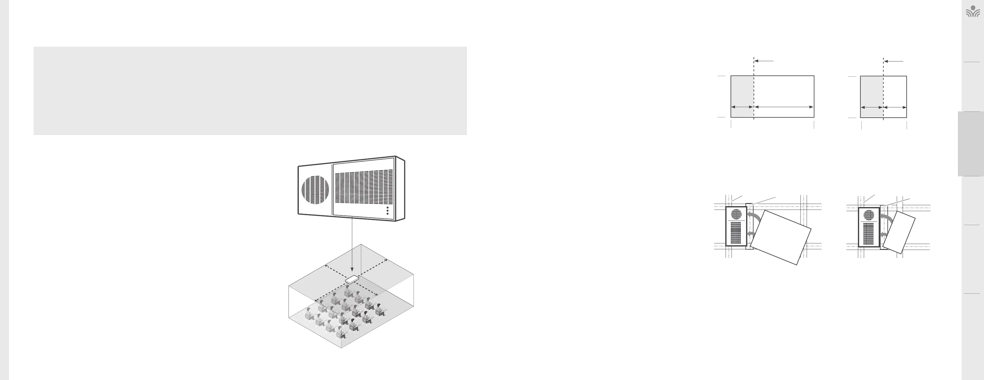
SELECTING SPEAKER MOUNTING LOCATIONS
One TCQ speaker will distribute sound throughout a classroom of up to 1,200 sq
(112 sq m). The location of the speaker is important to ensure even sound distribution.
Ceiling height should be 9 - 12 (2.75m - 3.75m).
1. Identify the center of the of the classroom for optimum location.
2. Select a ceiling tile that is free from fixtures (lighting, HVAC, etc.) within a 6 (1.8m)
radius nearest to the center point.
3. Remove the selected ceiling tile for speaker installation.
GRID CEILING INSTALLATION (U.S. & CANADA ONLY)
The dimensions of the TCQ are 1’ x 2’. It is designed to fit into any
standard 2’ X 4’, or 2’ X 2” suspended ceiling tile grid.
1. The ceiling tile will need to be cut to accommodate the TCQ
2. Set the ceiling tile on a flat work surface with the patterned side
facing down.
3. Using a straight edge, cut a 1’ x 2’ section from the ceiling tile,
creating a 1’ x 2’ section and a 3’ x 2’ section, or two 1’ x 2’
sections depending on the size of your tiles.
4. Locate the 2’ ceiling grid t-bar attachment. Locate the
attachment slots in the existing ceiling grid and snap the new
T-bar into place to create a 1’ x 2’ and 2’ x 3’ sections, or two 1’ x
2’ sections.
CUT THE ’ X ’ TILE TO CREATE A ’ X ’
SECTION AND A ’ X ’ SECTION.
WASTE REMAINING
/ CEILING TILE
CUT WITH
STRAIGHT EDGE
1’ 3’
2’
4’
’ X ’ CEILING TILE
CUT THE ’ X ’ TILE TO CREATE
TWO ’ X ’ SECTIONS
WASTE
CUT WITH
STRAIGHT EDGE
1' 1'
2’
2'
’ X ’ CEILING TILE
NEW T-BAR
EXISTING TILE GRID
/ TILE
SNAP THE T-BAR INTO PLACE TO
CREATE TWO ’ X ’ OPENINGS
TCQ
IDENTIFY THE CENTER OF THE ROOM