30 31
OVERVIEWINSTALLATION
PLANNING
SPEAKER LOCATION &
INSTALLATION
SET UP &
INTEGRATION
INSTALLING OPTIONAL
EQUIPMENT
TROUBLESHOOTING
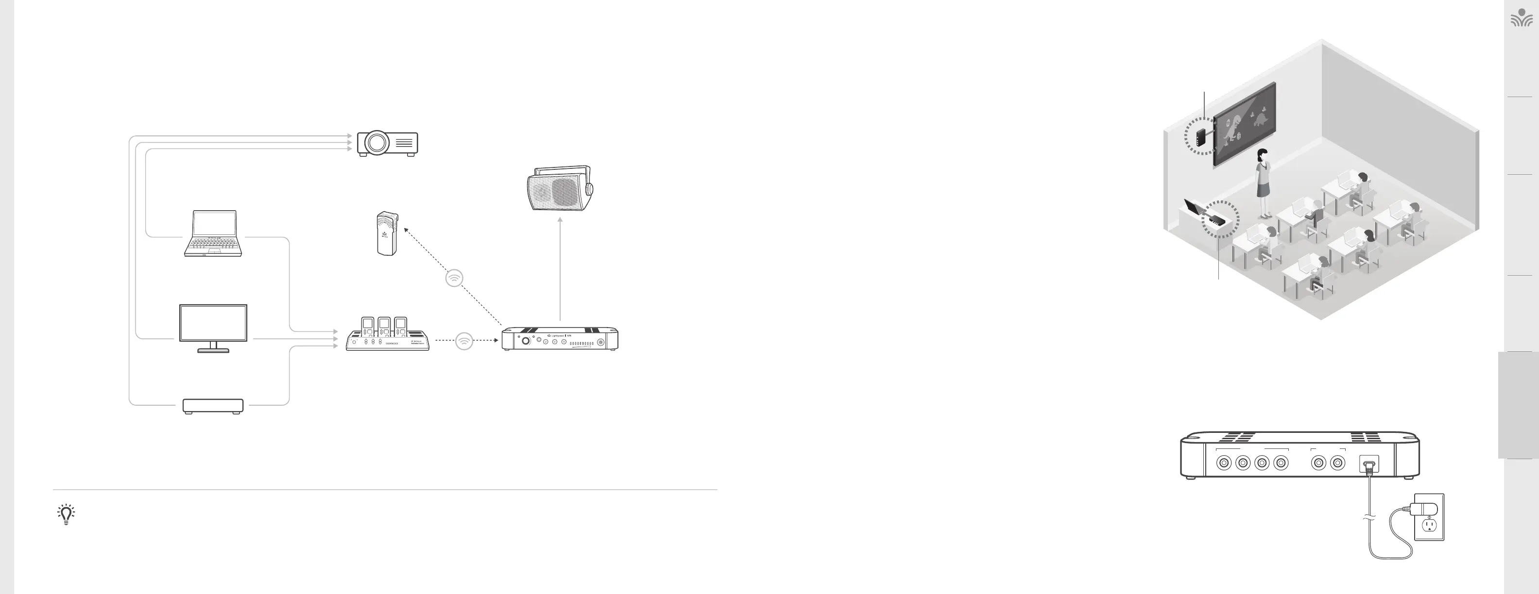
. OPTIONAL ACTIVATE AUDIO INTEGRATION
The Activate Station is designed to integrate with the 975 and multiple audio sources,
allowing other instructional technologies to be clearly heard throughout the classroom.
Audio
Input
Audio
Output
Audio
Output
Tone
Level
Push
StatusPower
PowerLink
InputOutput Mic
DVD
Video Out Audio Out
Video Out
Video In
Access Transmission
Access
Transmission
Audio Out
VGA Out Audio Out
Audio In
INTERACTIVE
DISPLAY
ACTIVATE STATION
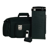
TEACHER’S
MICROPHONE
PROJECTOR
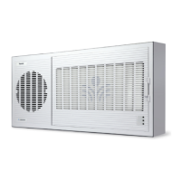
SPEAKER(S)
LAPTOP
NOTE ON INTEGRATION: If the Activate Station is not included in installation, a 3.5mm audio cable may be connected from the audio source to the audio input on the back of the
975. Take precautions as necessary to prevent and guard against electromagnetic and electrostatic noise interference. Long cable runs, unshielded and / or poorly shielded cable,
multiple ground paths and improper grounding may all contribute to the production of a low frequency hum. In most cases a ground loop isolator (not provided) placed in line will
attenuate or possibly eliminate the hum.
Media Connector Set-Up
. DETERMINE SET-UP LOCATION
• Choose a location for the Media Connector that is convenient to the classroom
audio sources and power supply.
• The Media Connector can be placed on a counter or wall mounted, 3-6 feet o
of the floor to allow for good transmission.
• If plugging in multimedia audio sources, it should be located in close proximity
to minimize cable runs.
• Note: Do not place in a fully enclosed metal cabinet
USB
5V / 0.2A
Audio Inputs
432
1
Audio Outputs
2
1
WALL MOUNTED
COUNTER OR DESK
. WALL MOUNTING THE MEDIA CONNECTOR
• Find a location on the wall that is near the computer or other equipment that will be
connected to the Media Connector.
• Power for the Media Connector must be within 6 of this location.
1. Hold Media Connector up to the wall and ensure that it is level. Mark the mounting
holes with a pencil. The back of the Media Connector that contains the inputs may be
mounted in any position that is desirable.
2. For sheetrock walls, use screw-in sheetrock anchors and screws (not supplied) to
secure the Media Connector to the wall. It is best to drill a 1/4” pilot hole at the two
mounting locations before inserting the anchors.
3. Once the anchors are installed, place the Media Connector over the mounting anchors
and insert the provided screws through the mounting holes and into the anchor.
4. If walls are concrete or cinder block, appropriate mounting hardware should be
purchased locally.
. CONNECT THE POWER SUPPLY
1. Connect the USB power supply to the USB port on the Media Connector.
2. Plug the USB power supply into an electrical outlet or plug the cable into a computer
USB port.
3. Press and hold the power-on button located on the front of the Media Connector to
power on and power o the unit.