www.lightware.eu Firmware version: 1.1.1
For technical support contact support@lightware.eu Document revision: 1.1
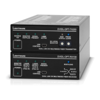
DVI-OPT-RX220-Pro
Quick Start Guide
Installation
1. Connect the DVI display devices to the DVI OUTPUT connectors.
2. Connect a compatible Lightware fiber transmitter unit with a multimode fiber cable to the
FIBER INPUT connector. Connect an LC optical cable to the “channel B” LC connector, or
use a Neutrik OpticalCON cable.
3. Power on the fiber transmitter, and the DVI source (computer).
4a. To use the built-in power supply: set the power selector switch to “I”, and connect the IEC
power cable. Now the unit is ready to be used.
4b. To power the unit remotely: works only if the receiver is connected to a
DVI-OPT-TX220-PRO with a Neutrik hybrid fiber cable. Set the power selector switch to “II”.
5. Power on the connected display devices. They will display the picture from the DVI source
(computer).
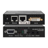
Lights if the unit is powered on.
Green light indicates that the laser is properly detected on
the optical input. Red blinking light indicates low laser level,
or no incoming signal.
Indicates valid DVI clock signal reception.
Each LED indicates if a display device is connected to the
corresponding DVI output.
Standard IEC power connector.
The break-out LC connector is internally connected to output
A of the Neutrik connector.
Channel B carries the signal to this unit’s optical receiver,
and channel A carries any optical signal to the break-out LC
connector.
The device is controllable by Lightware Matrix Control
software via RS-232 connection.
In position “I” the receiver unit is powered by its own built-in
power supply. In position “II” the receiver unit is powered
through special hybrid fiber cable, type’Neutrik 2M-4S75’.
Two display devices can be connected. The resolution and
pixel clock frequency are the same on both DVI connectors.
DVI signal detection and laser detection signals with ground
reference are available on a three-pole Phoenix connector.