Connect the power cord to the AC power socket to the matrix unit.
Powering the device is recommended as the nal step.
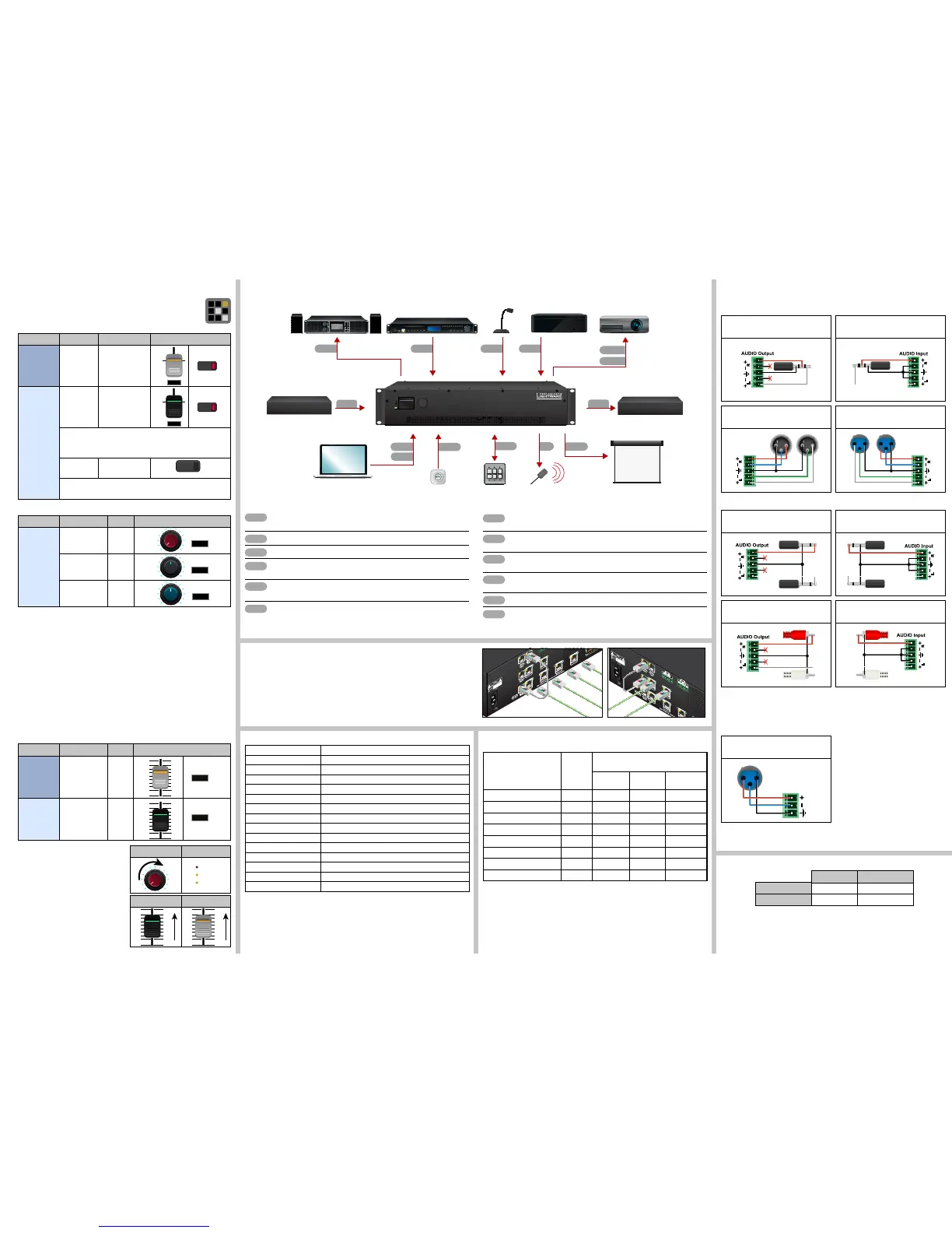
Maximum Extension Distances
Serial Output Voltage Levels (TTL and RS-232)
*Using a receiver with at least 1k impedance to any voltage between 0V and 5V to get the voltages,
but not compatible with the phased out TPS-90 extenders.
TTL* RS-232
Logic low level 0 .. 0.25V 3 V .. 15 V
Logic high level 4.75 .. 5.0V -15 V .. -3 V
Remote Powering (PoE)
The matrix is PoE-compatible (in accordance with IEEE 802.3af standard) and able to send
remote power to connected TPS devices via the TPS connection (through the CATx cable).
No local power adaptor is required for the connected PoE-compatible TPS extender. The PoE
feature is enabled on TPS ports as factory default.
Factory Default Settings
IP address 192.168.0.100
RS-232 port setting 57600 BAUD, 8, N, 1
Control protocol (RS-232) LW2
Crosspoint setting Input 1 on all outputs
I/O Ports Unmuted, unlocked
TPS mode Auto
PoE enable Enable
HDCP enable (input) Enable
HDCP mode (output) Auto
Signal Type Auto
Emulated EDID F47 - (Universal HDMI, all audio)
Audio mode HDMI audio passthrough
MIC input levels Volume (dB): 0.00; Panorama (Balance): 0; Gain (dB): 0.00
Analog audio input levels Volume (dB): 0.00; Balance: 0; Gain (dB): 0.00
Analog audio output levels Volume (dB): 0.00; Balance: 0
Ethernet Link to TPS inputs and TPS outputs
TPS lines do not transmit Ethernet signal, but they can be transmitted on the TPS input
and output ports, if there is a physical link between the motherboard and the input or the
output board. This makes possible to control a third-party device or supply Ethernet via TPS.
Connect a patch cable between
Ethernet Link to TPS inputs and TPS inputs Ethernet labeled RJ45 connectors or
Ethernet Link to TPS outputs and TPS outputs Ethernet labeled RJ45 connectors to
create a link.
Resolution
Pixel
clock rate
Cable lengths
(Auto / Long reach TPS mode)
CAT5e
AWG24
CAT7
AWG26
CAT7
AWG23
1024x768@60Hz 65 MHz 100 m / 130 m* 90 m / 120 m* 120 m / 170 m*
1280x720p@60Hz 73.8 MHz 100 m / 130 m* 90 m / 120 m* 120 m / 170 m*
1920x1080p@60Hz (24bpp) 148.5 MHz 100 m / 130 m* 90 m / 120 m* 120 m / 170 m*
1920x1200@60Hz 152.9 MHz 100 m / NA 90 m / NA 120 m / NA
1600x1200@60Hz 162 MHz 100 m / NA 90 m / NA 120 m / NA
1920x1080@60Hz (36bpp) 223 MHz 70 m / NA 70 m / NA 100 m / NA
3840x2160@30Hz UHD 297 MHz 70 m / NA 70 m / NA 100 m / NA
4096x2160@30Hz 4K 297 MHz 70 m / NA 70 m / NA 100 m / NA
* Long reach TPS mode supports pixel clock frequencies up to 148.5 MHz.
To specify the accurate extension distances, please also check the documentation of the
connected TPS device.
CAT7 SFTP AWG23 cable is always recommended.
Installation Guide for Connecting a Microphone
These settings can be done from a computer using the Lightware Device Controller
(LDC) software. The application is available at www.lightware.com, install it on a
Windows PC or a Mac OS X and connect to the device via LAN, USB, or RS-232.
1. Before the connection, please set these properties below:
Port Property Value Lightware Device Controller
Analog
audio output
(BAL. OUT)
Volume -80dB and/or Mute
Microphone
input
(MIC IN)
Volume -80dB and/or Mute
Skipping the volume or mute setting can cause serious
damage in the speaker or the external sound system when
phantom power is turned on!
Phantom
power
Turn off
Always turn off the phantom power before connecting the
microphone!
Port Property Value Lightware Device Controller
Microphone
input
(MIC IN)
Input gain -12dB
EQ (High,Hmid,
Lmid, Low)
0
Panorama 0
2. Connect the microphone.
a. In case of dynamic or wireless microphone: skip this step and follow the
instructions with step 3.
b. In case of condenser microphone: Switch on the phantom power. Keep pressed
the +48V button more than 2 seconds to activate phantom power.
Phantom power supplies the condenser microphone by 48V which is necessary
for normal operation. Application of the phantom power can cause a damage if
dynamic or wireless microphone is connected!
Always switch on the phantom power when the cabling and connecting have already
done. Do not disconnect the microphone when the phantom power is switched on!
3. Set these properties below:
Property Value Lightware Device Controller
Analog
audio output
(BAL.OUT)
Volume 0dB
Microphone
input
(MIC IN)
Volume 0dB
4. Talk to the microphone continuously.
Increase the microphone input gain slowly
and check the signal indicator chart. It gives
a feedback about the optimal signal level.
Take care that peak led (PK!) never lights up!
5. If the signal level is low, set the optimal
volume both the microphone input and
balanced output channel. Always check the
signal indicator chart for the optimal level!
Take care that peak led (PK!) never lights up!
MIC input gain MIC signal
MIC input volume Output volume
From balanced input to balanced output
1 x XLR - Phoenix
Always check the correct wiring
of the microphone cable! Never apply
phantom power with unbalanced cable,
because it can cause a damage!
Microphone cable should be shielded with
2x0,22mm conductor, max. 50m long.
For more information about audio cable wiring see the user’s manual of the device or the
Audio Cable Wiring Guide on our website www.lightware.com.
Made in EU, Hungary
50/60 Hz 1.4-0.85A
 Loading...