Factory Default Settings
IP address 192.168.0.100
LW3 / LW2 port number 6107 / 10001
Video I/O Ports Unmuted, unlocked
Crosspoint setting Input 1 on all outputs
HDCP enable (input) Enable
HDCP mode (output) Auto
Signal Type Auto
Power 5V mode Auto
Emulated EDID F47 - (Universal HDMI, all audio)
Audio mode HDMI audio passthrough
Analog audio input levels Volume (dB): 0.00; Balance: 0; Gain (dB): 0.00
Analog audio output levels Volume (dB): 0.00; Balance: 0
RS-232 port setting 57600 BAUD, 8, N, 1, Command injection mode
Control protocol (RS-232) LW2
RS-232 port nr. 8001, 8002, 8003, 8004
IR operation mode Command injection mode
IR port nr. 9001, 9002, 9003, 9004
Switching Operations
1. First press and release the desired source button.
The pressed source button and all destination buttons
which are currently connected to the source lights up.
SOURCES
DESTINATIONS
2. Press and release the desired destination buttons
which have to be (dis)connected to/from the selected
source. The preselected destination buttons will blink.
SOURCES
DESTINATIONS
3. Press and release Take button; the selected input is
switched to the selected output(s).
Locking an Output
1. Press and release the Output Lock button; it starts to
blink and all the buttons of any locked destinations light
up (view state).
OUTPUT
LOCK
CONTROL
LOCK
2. Press and release a destination button; it starts to
blink (more destinations can be selected sequentially).
OUTPUT
LOCK
CONTROL
LOCK
3. Press and release the Take button. The selected
destinations are now locked.
Switching and Locking Operations in TAKE Mode
Take mode allows the user to connect or disconnect multiple outputs to an input at
once. This mode is useful when multiple switching is necessary. The commands
are only realized when the Take button is pressed.
TAKE
AUTO
Switching Operations
1. Press and release the desired destination button.
The pressed destination button and the actually
connected source button light up green. If no source is
connected (the output is muted) no source button will
light up.
SOURCES
DESTINATIONS
2. Press and release the desired source button. The
switch action will be executed immediately. Switching
between sources to the selected destination can be done
directly.
SOURCES
DESTINATIONS
Locking an Output
1. Press and release the required destination button.
Now the selected destination button and the currently
congured source button light up (view mode).
OUTPUT
LOCK
CONTROL
LOCK
2. Press and release the Output Lock button; it lights up
in red, and lock function is activated at once. No source
can be changed at the locked destination.
OUTPUT
LOCK
CONTROL
LOCK
Front Panel Operations - Buttons
Switching and Locking Operations in AUTOTAKE Mode
Autotake mode is useful when immediate actions must be done or fast switching
is needed between sources on a particular destination. In this mode switching
occurs immediately upon pressing one of the input selector buttons.
TAKE
AUTO
Pin assignment of 2-pole IR emitter connector (1/8” TS)
1 Tip +5V
2 Ring
Signal (active low)
3 Sleeve
Front Panel Operations - LCD Menu and Navigation
The front panel has a color LCD showing the most important settings and parameters. The jog
dial control knob can be used to navigate between the menu items or change the value of a
parameter. The knob can be pressed to enter a menu or edit/set a parameter.
Software Control – Using Lightware Device Controller (LDC)
The device can be controlled from a computer using the Lightware Device
Controller software. The application is available at www.lightware.com, install
it on a Windows PC or a Mac OS X and connect to the device via LAN, USB,
or RS-232.
Firmware Upgrade
Lightware Device Updater (LDU) is an easy and comfortable way to keep
your device up to date. Establish the connection via Ethernet. Download and
install LDU software from the company’s website www.lightware.com where
you can nd the latest rmware package as well.
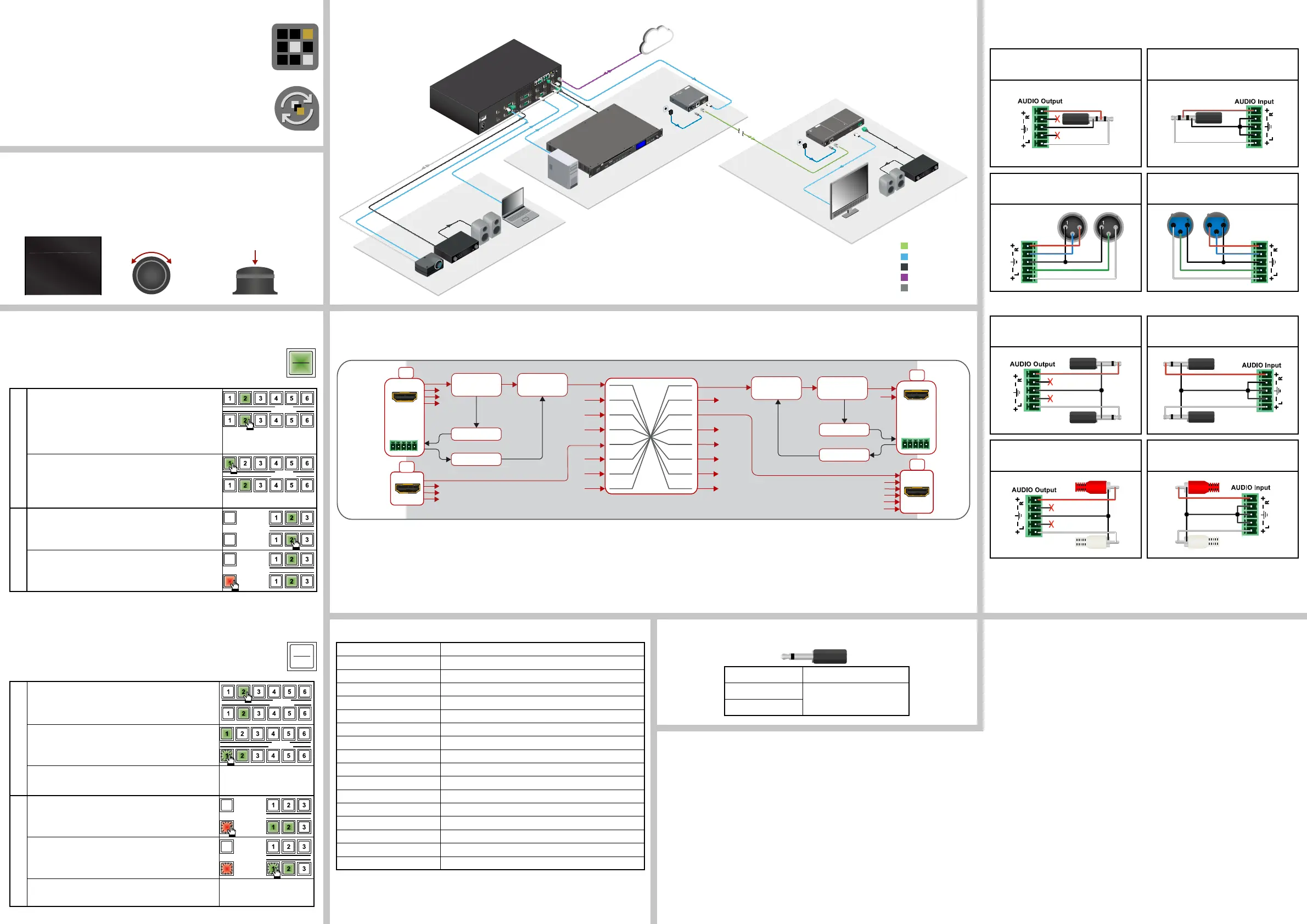
Audio Cable Wiring Guide
MMX8x4 series matrix is built with 5-pole Phoenix input and output connectors. See below a
few example of the most common assembling cases.
From balanced output to unbalanced input
Phoenix - 3.5 (1/8”) TRS
From unbalanced output to balanced input
3.5 (1/8”) TRS - Phoenix
From balanced output to balanced input
Phoenix - 2 x XLR
From balanced output to balanced input
2 x XLR - Phoenix
2
3
2
3
2
3
2
3
From balanced output to unbalanced input
Phoenix - 2 x 6.3 (1/4”) TS
From unbalanced output to balanced input
2 x 6.3 (1/4”) TS - Phoenix
From balanced output to unbalanced input
Phoenix - 2 x RCA
From unbalanced output to balanced input
2 x RCA - Phoenix
MAIN MENU
> System Settings
Ports
EDID
Menu navigation
& change parameter
Menu selection
& set parameter
Press
Turn
D/A converter
HDMI Crosspoint 8x8
6x
2x
ADC
HDMI
out
HDMI in
4x
AUX
analog
audio I/O
HDMI in
4x
HDMI
out
AUX
analog
audio
I/O
Audio
embedder
Audio
de- embedder
ADC
Audio
de- embedder
Audio
embedder
A/D converter
D/A converter
A/D converter
Made in EU, Hungary
50/60 Hz 1.4-0.85A
100-240 VAC
Sn:
Reset
3
4
RX TX RX TX
2 1
TX TX
4
RS232
2 1
3
AUDIO I/O
HDMI OUT 1
HDMI OUT 2
HDMI OUT 3
HDMI OUT 4
HDMI OUT 5
HDMI OUT 6
HDMI OUT 7
HDMI OUT 8
HDMI IN 1
HDMI IN 2
HDMI IN 3
HDMI IN 4
HDMI IN 5
HDMI IN 6
HDMI IN 7
HDMI IN 8
AUDIO I/O
AUDIO I/O
AUDIO I/O
AUDIO I/O
AUDIO I/O
IR OUT
ETHERNET
Media player
PC
Laptop
Speakers
Power
amplifier
MMX8x8-HDMI-4K-A
TPS
HDMI
Analog audio
LAN
RS-232
Sn:
Made in EU, Hungary
RoHS
Ethernet 10/100
Bidirectional IR
Bidirectional RS-232
TTPPSS LLoonngg DDiissttaannccee TTrraannssmmiitttteerr
HDMI, 3D, 4K supported
For best performance use AWG23 CAT6 or CAT7 SFTP cable
PIN: 2mm
12V 1A DC
H
D
M
I
--T
P
S
--T
X
9
7
Device can be remote powered over TPS link with PoE
(IEEE 802.3af)
TPS OUT
PoE
( )
TPS
(up to 170 m)
12V DC
1.5A
---
_
PIN: 2mm
12V DC
1.5A
---
_
AUDIO OUT
HDMI OUT
SIGNAL AUDIO
TPS IN (PoE)
TPS Receiver with Relay modules and Audio de-embedding
HHDDMMII--TTPPSS--RRXX111100AAYY
Made in EU, Hungary
RoHS
For best performance use AWG23
CAT6 or CAT7 SFTP cable
Device can be remote powered over TPS link with PoE
(IEEE 802.3af)
Sn:
Front LEDs
LIVE
RS-232
Fast blinking (0.5 sec): Firmware upgrade mode
ON: Powered but no operation
OFF: No power
OFF: Pass-through mode
Blinking (1 sec): Normal operation
Blinking: Command Injection mode
ON: Control mode
OFF: No TPS link
TPS LINK
Blinking: Low power mode
ON: TPS link active
AUDIO OUT
OFF: Embedded audio not present or muted
Blinking: Embedded audio format not supported
for audio de-emebedding
ON: Embedded audio present and de-embedded
HDCP
Blinking: Non HDCP capable device connected,
encrypted signal replaced with red screen
Rear LEDs
SIGNAL
ON: Signal present
OFF: Output signal not present or muted
TPS INPUT
HDMI OUTPUT
OFF: Output signal not HDCP encrypted
ON: Output signal HDCP encrypted
- Remote power (PoE)
- TPS Link
Power
amplifier
Speakers
Monitor
HDMI-TPS-RX110AY
1 2 3 4 5 6 7 8
PUSH TO EJECT
CD / USB / SD / AU X / BT / F M / AM
EJECT
SD
TEXT
LOCK
ALL/
FOLDER
RANDOM
REPEAT
AUX IN
POWER
USB
CD/USB/SD
AUX/ BT
STOP
PLAY
BT AAC
2 00:03 :16
HDMI-TPS-TX97
Huddle room 2.
Server room
RS-232
HDMI
HDMI
Analog
audio
Analog audio
Analog audio
HDMI
HDMI
HDMI
LAN
Typical Application
Port Diagram
 Loading...