Quick Start Guide
VINX-110-HDMI-DEC
VINX-120-HDMI-ENC
Further Information
The document is valid with the following rmware version: 1.1.0
The User’s manual of this appliance is available on www.lightware.com.
See the Downloads section on the website of the product.
Contact Us
sales@lightware.com
+36 1 255 3800
support@lightware.com
+36 1 255 3810
Lightware Visual Engineering LLC.
Peterdy 15, Budapest H-1071, Hungary
Doc. ver.: 1.1
19200084
Important Safety Instructions
Please read and keep the information in the attached safety instructions supplied with the
product before you start using the device.
Introduction
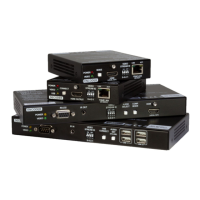
VINX-120-HDMI-ENC and VINX-110-HDMI-DEC encoder/decoder multimedia extenders to
extend HDMI video from a local source to a remote sink. The devices can be connected
either via a direct CATx cable connection or through a Gigabit Ethernet Switch (L3-switch is
necessary) in between. The maximum delivery distance can reach up to 100 m with minimal
latency and employ a quality, proprietary wavelet transform based image compression.
The maximum supported resolution is 3840 x 2160 @ 30Hz with 7.1 audio and scaling
is available on the receiver side with optional image cropping. Optionally, bidirectional
RS-232 signal transmission, USB Mass storage and Human Interface Device (HID*) signal
transmission is also available.
* HID: USB mouse, keyboard, presenter, etc.
Compatible Devices
The signal transmission works only between these Encoder and Decoder devices, other
Lightware devices cannot be connected to the 1GbE LAN (AV input/output) ports.
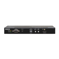
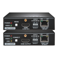
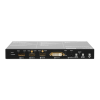
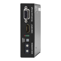
Encoder – Front View and Rear View
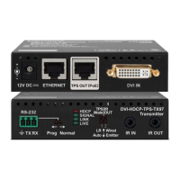
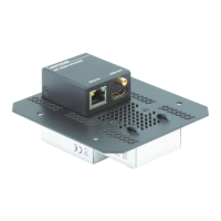
Decoder – Front View and Rear View
Box Contents
1
Supplied with the Decoder
2
Supplied with the Encoder
3
Optional accessory
Connecting Steps (Multicast Mode)
Arrange the Encoder and the desired Decoder devices.
Encoder/Decoder device 5V DC Power Adaptor with
interchangeable plugs
Safety and Warranty info,
Quick Start Guide
USB Cable
(mini-B to B-type)
HDMI Cable
(male to male)
Serial Cable
2
(DE-9 male to RJ12)
Infrared
Transmitter Unit
3
Infrared
Receiver Unit
3
Serial Cable
1
(DE9 female to RJ12)
1
Status LEDs See the attached list.
2
Mode Button Short press (less, than 3 sec): switching between the
Video and Graphic modes.
Long press (more, than 3 sec): reset to factory default
settings.
3
HDMI Output
Port
Forwarding the same Audio / Video content as the AV
Output Port.
4
DIP Switch Linking Encoder and Decoder devices (HW setting).
5
AV Output Port RJ45 connector for outgoing A/V signal to the Decoder
device(s) or Network switch.
6
DC 5V Input 5V DC input for local power supply.
7
RS-232 Port RJ12 connector for transparent serial communication
(point-to-point or point-to-multi point).
8
USB Port Mini B-type connector for USB pass-through application.
9
HDMI Input Port Video port for DVI or HDMI signal.
q
IR Output Port IR signal output connector (for 3.5 mm Jack, 3-pole, TRS
plug).
1
Status LEDs See the attached list.
2
Connect Button Short press (less, than 3 sec): acquire USB connection
(only in Multicast mode).
Long press (more, than 3 sec): reset to factory default
settings.
3
HDMI Output
Port
HDMI output to a sink device.
4
DIP Switch Linking Encoder and Decoder devices (HW setting).
5
AV Input Port RJ45 connector for incoming A/V signal from the Encoder
device or Network switch.
6
DC 5V Input 5V DC input for local power supply.
7
RS-232 Port RJ12 connector for transparent serial communication
(point-to-point or point-to-multi point).
8
USB Ports USB 1.1 and 2.0 compatible A-type ports for transmitting
USB HID devices in Unicast mode.
9
IR Input Port IR signal input connector (for 3.5 mm Jack, 3-pole, TRS
plug).
Status LEDs
Power LED
OFF: no power source is connected to the device.
BLINKING: the device is booting.
ON: the device is powered.
Video LED
OFF: the device is not connected to a network.
BLINKING: the unit is connected to a network but no video streaming is in progress.
ON: the unit is connected to a network and video streaming is in progress.
Power and Video LEDs
BLINKING together: there is a Video Stream ID clash in the network.
USB LED
OFF: there is no USB connection between the Encoder and the Decoder devices.
ON: there is a USB connection between the Encoder and the Decoder devices.
USB connection shall be acquired in the Decoder in Multicast mode. In Unicast mode, the
USB connection is set up automatically.
Mounting Options
To mount the device Lightware supplies optional accessories for different usage:
VESA100 Mounting adapter for extenders
Under-desk mounting kit
Under-desk double mounting kit
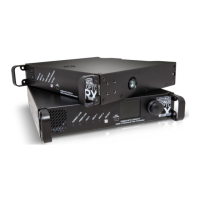
1U high rack shelf
To order mounting accessory kits please contact sales@lightware.com.
Mounting by Using the VESA100 Mounting adapter for extenders
Two mounting holes can be found at the bottom of the extender at each side, the VESA-
compatible accessory plate can xed as indicated. The other two holes of the plate can be
xed to a VESA-compatible device (e.g. rear panel of an HDTV).
First of all, please set the parameters of the L3 Switch to meet with the requirements.
Please turn the paper to see the list in the ‘Preparing the Network’ section.