Device Concept
The following signals are transmitted between the Encoder and the Decoder devices:
The USB, Serial, and IR data transmission is working independently from the video signal
presence.
Arranging the Extenders to Groups
Encoder and Decoder devices have to be assigned to each other in order to transfer the
desired video and control signals – by any of the following ways:
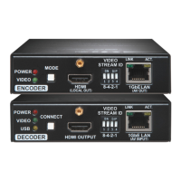
1. HW setting: use the DIP switch at the front
panel to set the Video stream ID: set the DIP
switch states to the same value at the desired
devices. If you set a DIP switch at a device, the other devices can be congured via the
web page. Please note that the value of DIP switch assigned Video Stream ID can range
from 1 to 15 inclusive.
2. SW setting: set the Video stream ID via the built-in web
page. Connect to the device as described in the Software
Control section. The Video Stream ID shall be between 1
and 65535 inclusive. In this case make sure that the DIP switches of the affected devices
are set to ‘0000’.
Video Stream ID Rules
The following rules are dened to avoid Video Stream ID conicts:
When the DIP switch is in ‘0000’ position the SW setting will be valid.
When the DIP switch is not in ‘0000’ position the HW setting will be valid.
When the DIP switch is set back to ‘0000’ the SW setting will inherit the ID (the previous
DIP switch value).
SW setting and HW setting can be combined within the group but in this case the DIP
switch value will determine the common Video Stream ID.
The DIP switch state can be ignored by an LW3 command, see the User’s Manual.
IP address Dynamic (DHCP is enabled)
RS-232 port setting 115200 BAUD, 8, N, 1
DIP Switch state 0000
Video stream ID 1
Connecting method Multicast mode
Emulated EDID F47 (Universal HDMI EDID) *
User EDID memory Empty (cleared)
Output video mode (Encoder) Video mode
Output scaling (Decoder) Pass-through, no rotation
Defined video walls Empty (cleared)
Supported Resolutions
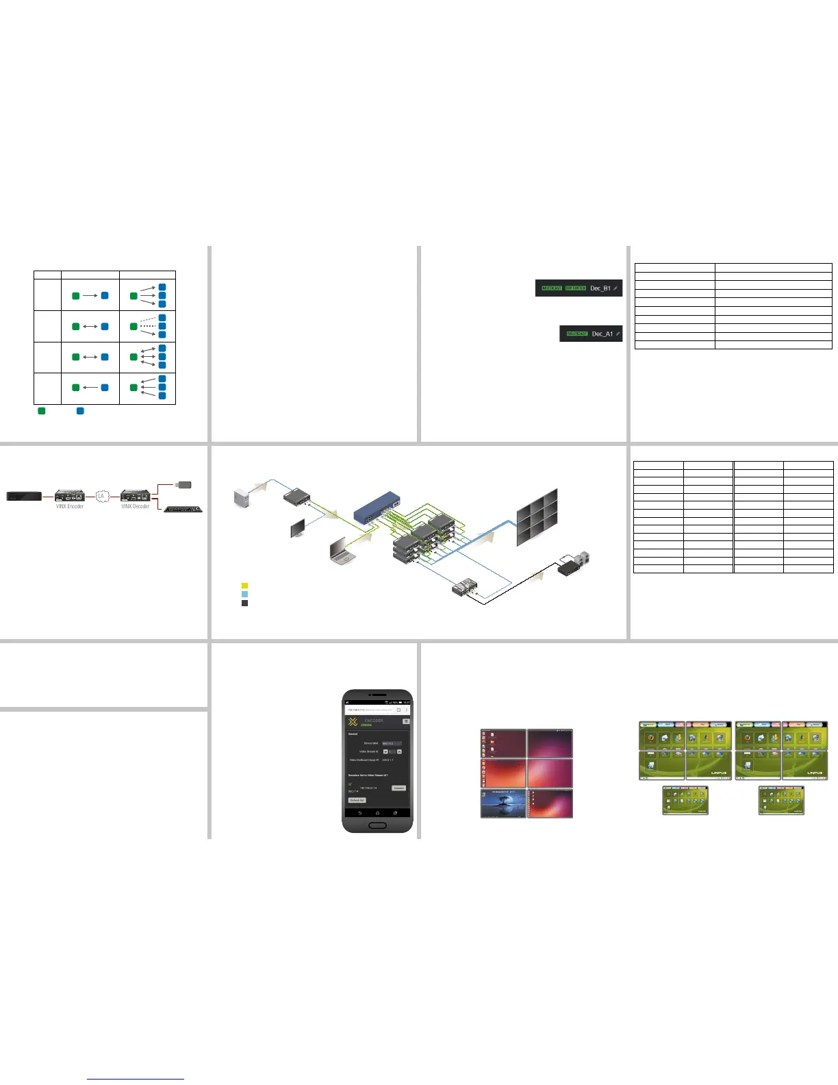
Two Video Walls and Local Monitors with One Encoder
Features of the system:
One Encoder is enough to supply the Decoders.
Displaying one video signal on two different video walls (e.g. in different rooms).
Displaying the video signal on 1-1 single sinks.
Factory Default Settings
* Most of the factory preset EDIDs include only one resolution. This is to force the connected
source to give a signal with the needed resolution. The Universal EDID allows many common
resolutions; the preferred timing is 1920x1080p60 with 2ch LPCM audio support.
Video Wall Layout Examples
The following examples show how the VINX devices can be arranged to video wall applications.
See more details in the User’s Manual available at www.lightware.com.
Multicast Mode with Video Wall
Features of the system:
Displaying one of the two video signals on the video wall and on a sink.
Displaying the other video signal on a sink.
The other video signal can be displayed on the video wall by using software tools (built-in
web or LW3 protocol commands).
Typical Application
Software Control – by Using the Built-in Webpage
When the device and a computer are connected to the same network, the VINX can be
congured via a web browser (Google Chrome and Mozilla Firefox are recommended):
1. Arrange the desired extenders with source/sink devices.
2. Connect the extenders to the network switch and
power them on.
3. Connect a suitable control device (e.g. computer,
mobile device) to the same network.
4. Open the web browser and type the IP address of
the desired device in the address line. If the address
is not known try any of the followings:
a. The factory default IP address is Dynamic
(DHCP). Check the list of the connected
devices (DHCP client list) on the DHCP server
and note the IP address.
b. In the case of a Decoder, type the
following in the address line:
http://LWR-clientAABBCCDDEEFF.local
c. In the case of an Encoder, Type the
following in the address line:
http://LWR-gatewayAABBCCDDEEFF.local
AABBCCDDEEFF is the MAC address of the
device (without hyphens) – which can be seen
on the housing of the extender.
Resolution Refresh Rate (Hz) Resolution Refresh Rate (Hz)
640 x 480 50/59/60/72/75 1440 x 900 59/60/75
720 x 480 (480P) 50/59/60/75 1600 x 900 59/60
720 x 576 (576P) 50 1600 x 1024 59/60
800 x 600 50/59/60/72/75 1600 x 1200 50/59/60
1024 x 768 50/60/75 1680 x 1050 50/59/60
1152 x 864 60 1920 x 1080i 25
1280 x 720 (720p) 50/59/60/75 1920 x 1080 (1080P) 50/59/60
1280 x 768 50/59/60/75 1920 x 1200 50/60
1280 x 800 59/60/75 2560 x 1080 24/25/30/60
1280 x 960 50/59/60 2560 x 1200 30/60
1280 x 1024 50/59/60/75 2560 x 1600 60
1360 x 768 50/59/60/75 3840 x 2160 24/25/30
1366 x 768 59/60 4096 x 2160 24/25/30
Preparing the Network – The Requirements of the Switch
The recommended type of network device: 1GbE network with Layer 3 switch, Gigabit
Ethernet. In TCP/IP terminology Layer 2 is the data link layer that is responsible for splitting
up the information coming from higher layers in the TCP/IP stack into Ethernet frames. An
Ethernet frame contains labeling information with source and destination physical addresses
(called source and destination MAC address). These physical addresses uniquely identify
the source and destination physical devices (e.g. a VINX encoder and a VINX decoder).
Ethernet frames provide error resilience by incorporating a redundancy check eld through
which transmission errors can easily be detected. The device that does uses only the physical
address information found in the Ethernet frame to root the packet from one of its input ports
to one or more of it output ports is an unmanaged switch.
A managed switch, on the other hand, can handle the trafc and forward input packets to
output packets by utilizing information from higher layers. This gives the managed switch more
exibility and also allows for more sophisticated functions like multicast forwarding. Since even
a simple VINX network where one VINX encoder supplies more VINX decoders relies on
multicasting, a multicast capable switch (i.e. a managed one) is a must. The managed switch
shall offer the following capabilities:
IGMPv2
IGMP snooping, IGMP fast leave, IGMP querier
Multicast ltering
Jumbo frames
For more information about the requirements and technologies please see the Application
Note at the website of the product.
USB Transmission
The USB data transmission works as shown in the gure below. The USB devices are
connected to the Decoder, the host device (computer) is connected to the Encoder by the
supplied USB cable.
Supported Devices
USB HID devices (keyboard, mouse, presenter, etc.) and mass storage devices (ash drive,
external hard drive).
Establishing the Connection
The data transmission is working always between an Encoder and a Decoder. In Unicast
mode (one Encoder and one Decoder) the transmission is enabled automatically. When the
extenders are in Multicast mode the desired Decoder can be selected by:
Pressing the Connect button at the front panel of the Decoder, or
Pressing the Acquire USB connection button via the built-in website of the Decoder
(Advanced Settings).
Thus, the USB ports of the active Decoder are working as the ports of an extended USB hub.
The data communication of the USB devices connected to the other Decoders is
suspended, however, they are still powered over USB.
RS-232 Transmission
The RS-232 serial data transmission is fully transparent between the Encoder and the
connected Decoder devices. All data received at the serial port of the Decoders is transmitted
to the serial port of the Encoder and vice versa: the data received at the serial port of the
Encoder is transmitted to the serial port of all connected Decoders.
The data transmission works only if the serial port parameters set to the same values in all
the devices: serial data sender/receiver and the VINX Encoder and Decoder devices.
Video Transmission Quality
When the network bandwidth is not enough to transmit the video signal the following modes
are available in the Encoder:
Video mode (Lower image quality @ Less bandwidth): The image quality is adjusted to
the available bandwidth. If the bandwidth is decreased the image quality will be lower, but
the video streaming is continuous.
Graphics mode (Best image quality @ High bandwidth): The image quality is kept at a
high level. If the bandwidth is decreased the image quality does not change, but frame
drop may appear.
The setting has an affect when the available bandwidth is less than required.
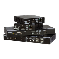
PC1
Video (4K@30Hz)
VINX-120-HDMI-ENC
VINX-110-HDMI-DEC
16-port L3 Switch
Control Laptop
1-output decoder with HDMI connector
HDMI 1.4
Infra port
Bidirectional RS-232
USB HID extension
CONNECT but ton (f or fur the r d eta ils ple ase se e t he Use r's ma nua l)
Short pr ess : Ac qui re USB co nne cti on in mul tic ast mod e
Long pre ss: Re set to fa cto ry def ault s
Video Strea m I D
0: Recei ve str eam wi th Vide o S tre am ID set vi a s oft war e
1-15: Recei ve str eam wi th fix ed Vide o S tre am ID set by th e s wit ch
Front LEDs
POWER
OFF: No pow er
Blinking : B oot ing
Continuo us: Po wer co nne cte d
VIDEO
OFF: No con nec tio n w ith EN COD ER
Blinking : C onn ect ed to ENC ODE R, no v ide o o utp ut
Continuo us: Co nne cte d t o E NCO DER, vi deo ou tpu t
USB
OFF:No U SB con nec tio n
Continuo us: US B c onn ect ion aq uir ed
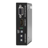
VINX-110-HDMI-DEC
HDMI OUTPUT
CONNECT
POWER
VIDEO
USB
1GbE LAN
(AV INPUT)
CHANNEL ID
ON DIP
LINK ACT.
123 4
8-4-2-1
DECODER
1-output decoder with HDMI connector
HDMI 1.4
Infra port
Bidirectional RS-232
USB HID extension
CONNECT but ton (f or fur the r d eta ils ple ase se e t he Use r's ma nua l)
Short pr ess : Ac qui re USB co nne cti on in mul tic ast mod e
Long pre ss: Re set to fa cto ry def ault s
Video Strea m I D
0: Recei ve str eam wi th Vid eo S tre am ID set vi a s oft war e
1-15: Recei ve str eam wi th fix ed Vide o S tre am ID set by th e s wit ch
Front LEDs
POWER
OFF: No pow er
Blinking : B oot ing
Continuo us: Po wer co nne cte d
VIDEO
OFF: No con nec tio n w ith EN COD ER
Blinking : C onn ect ed to ENC ODE R, no v ide o o utp ut
Continuo us: Co nne cte d t o E NCO DER , vi deo ou tpu t
USB
OFF:No U SB con nec tio n
Continuo us: US B c onn ect ion aq uir ed
VINX-110-HDMI-DEC
HDMI OUTPUT
CONNECT
POWER
VIDEO
USB
1GbE LAN
(AV INPUT)
CHANNEL ID
ON DIP
LINK ACT.
123 4
8-4-2-1
DECODER
1-output decoder with HDMI connector
HDMI 1.4
Infra port
Bidirectional RS-232
USB HID extension
CONNECT but ton (f or fur the r d eta ils ple ase se e t he Use r's ma nua l)
Short pr ess : Ac qui re USB co nne cti on in mul tic ast mod e
Long pre ss: Re set to fa cto ry def ault s
Video Strea m I D
0: Recei ve str eam wi th Vide o S tre am ID set vi a s oft war e
1-15: Recei ve str eam wi th fix ed Vide o S tre am ID set by th e s wit ch
Front LEDs
POWER
OFF: No pow er
Blinking : B oot ing
Continuo us: Po wer co nne cte d
VIDEO
OFF: No con nec tio n w ith EN COD ER
Blinking : C onn ect ed to ENC ODE R, no v ide o o utp ut
Continuo us: Co nne cte d t o E NCO DER, vi deo ou tpu t
USB
OFF:No U SB con nec tio n
Continuo us: US B c onn ect ion aq uire d
VINX-110-HDMI-DEC
HDMI OUTPUT
CONNECT
POWER
VIDEO
USB
1GbE LAN
(AV INPUT)
CHANNEL ID
ON DIP
LINK ACT.
123 4
8-4-2-1
DECODER
1-output decoder with HDMI connector
HDMI 1.4
Infra port
Bidirectional RS-232
USB HID extension
CONNECT but ton (f or fur the r d eta ils ple ase se e t he Use r's ma nua l)
Short pr ess : Ac qui re USB co nne cti on in mul tic ast mod e
Long pre ss: Re set to fa cto ry def ault s
Video Strea m I D
0: Recei ve str eam wi th Vid eo S tre am ID set vi a s oft war e
1-15: Recei ve str eam wi th fix ed Vide o S tre am ID set by th e s wit ch
Front LEDs
POWER
OFF: No pow er
Blinking : B oot ing
Continuo us: Po wer co nne cte d
VIDEO
OFF: No con nec tio n w ith EN COD ER
Blinking : C onn ect ed to ENC ODE R, no v ide o o utp ut
Continuo us: Co nne cte d t o E NCO DER, vi deo ou tpu t
USB
OFF:No U SB con nec tio n
Continuo us: US B c onn ect ion aq uir ed
VINX-110-HDMI-DEC
HDMI OUTPUT
CONNECT
POWER
VIDEO
USB
1GbE LAN
(AV INPUT)
CHANNEL ID
ON DIP
LINK ACT.
123 4
8-4-2-1
DECODER
1-output decoder with HDMI connector
HDMI 1.4
Infra port
Bidirectional RS-232
USB HID extension
CONNECT but ton (f or fur the r d eta ils ple ase se e t he Use r's ma nua l)
Short pr ess : Ac qui re USB co nne cti on in mul tic ast mod e
Long pre ss: Re set to fa cto ry def ault s
Video Strea m I D
0: Recei ve str eam wi th Vide o S tre am ID set vi a s oft war e
1-15: Recei ve str eam wi th fix ed Vide o S tre am ID set by th e s wit ch
Front LEDs
POWER
OFF: No pow er
Blinking : B oot ing
Continuo us: Po wer co nne cte d
VIDEO
OFF: No con nec tio n w ith EN COD ER
Blinking : C onn ect ed to ENC ODE R, no v ide o o utp ut
Continuo us: Co nne cte d t o E NCO DER, vi deo ou tpu t
USB
OFF:No U SB con nec tio n
Continuo us: US B c onn ect ion aq uire d
VINX-110-HDMI-DEC
HDMI OUTPUT
CONNECT
POWER
VIDEO
USB
1GbE LAN
(AV INPUT)
VIDEO
STREAM ID
ON DIP
LINK ACT.
123 4
8-4-2-1
DECODER
1-output decoder with HDMI connector
HDMI 1.4
Infra port
Bidirectional RS-232
USB HID extension
CONNECT but ton (f or fur the r d eta ils ple ase se e t he Use r's ma nua l)
Short pr ess : Ac qui re USB co nne cti on in mul tic ast mod e
Long pre ss: Re set to fa cto ry def ault s
Video Strea m I D
0: Recei ve str eam wi th Vide o S tre am ID set vi a s oft war e
1-15: Recei ve str eam wi th fix ed Vide o S tre am ID set by th e s wit ch
Front LEDs
POWER
OFF: No pow er
Blinking : B oot ing
Continuo us: Po wer co nne cte d
VIDEO
OFF: No con nec tio n w ith EN COD ER
Blinking : C onn ect ed to ENC ODE R, no v ide o o utp ut
Continuo us: Co nne cte d t o E NCO DER, vi deo ou tpu t
USB
OFF:No U SB con nec tio n
Continuo us: US B c onn ect ion aq uir ed
VINX-110-HDMI-DEC
HDMI OUTPUT
CONNECT
POWER
VIDEO
USB
1GbE LAN
(AV INPUT)
CHANNEL ID
ON DIP
LINK ACT.
123 4
8-4-2-1
DECODER
CATx
HDMI
Analog audio
1-output decoder with HDMI connector
HDMI 1.4
Infra port
Bidirectional RS-232
USB HID extension
CONNECT but ton (f or fur the r d eta ils ple ase se e t he Use r's ma nua l)
Short pr ess : Ac qui re USB co nne cti on in mul tic ast mod e
Long pre ss: Re set to fa cto ry def ault s
Video Strea m I D
0: Recei ve str eam wi th Vide o S tre am ID set vi a s oft war e
1-15: Recei ve str eam wi th fix ed Vide o S tre am ID set by th e s wit ch
Front LEDs
POWER
OFF: No pow er
Blinking : B oot ing
Continuo us: Po wer co nne cte d
VIDEO
OFF: No con nec tio n w ith EN COD ER
Blinking : C onn ect ed to ENC ODE R, no v ide o o utp ut
Continuo us: Co nne cte d t o E NCO DER, vi deo ou tpu t
USB
OFF:No U SB con nec tio n
Continuo us: US B c onn ect ion aq uir ed
VINX-110-HDMI-DEC
HDMI OUTPUT
CONNECT
POWER
VIDEO
USB
1GbE LAN
(AV INPUT)
CHANNEL ID
ON DIP
LINK ACT.
123 4
8-4-2-1
DECODER
1-output decoder with HDMI connector
HDMI 1.4
Infra port
Bidirectional RS-232
USB HID extension
CONNECT but ton (f or fur the r d eta ils ple ase se e t he Use r's ma nua l)
Short pr ess : Ac qui re USB co nne cti on in mul tic ast mod e
Long pre ss: Re set to fa cto ry def ault s
Video Strea m I D
0: Recei ve str eam wi th Vide o S tre am ID set vi a s oft war e
1-15: Recei ve str eam wi th fix ed Vide o S tre am ID set by th e s wit ch
Front LEDs
POWER
OFF: No pow er
Blinking : B oot ing
Continuo us: Po wer co nne cte d
VIDEO
OFF: No con nec tio n w ith EN COD ER
Blinking : C onn ect ed to ENC ODE R, no v ide o o utp ut
Continuo us: Co nne cte d t o E NCO DER, vi deo ou tpu t
USB
OFF:No U SB con nec tio n
Continuo us: US B c onn ect ion aq uir ed
VINX-110-HDMI-DEC
HDMI OUTPUT
CONNECT
POWER
VIDEO
USB
1GbE LAN
(AV INPUT)
VIDEO
STREAM ID
ON DIP
LINK ACT.
123 4
8-4-2-1
DECODER
1-output decoder with HDMI connector
HDMI 1.4
Infra port
Bidirectional RS-232
USB HID extension
CONNECT but ton (f or fur the r d eta ils ple ase se e t he Use r's ma nua l)
Short pr ess : Ac qui re USB co nne cti on in mul tic ast mod e
Long pre ss: Re set to fa cto ry def ault s
Video Strea m I D
0: Recei ve str eam wi th Vid eo S tre am ID set vi a s oft war e
1-15: Recei ve str eam wi th fix ed Vide o S tre am ID set by th e s wit ch
Front LEDs
POWER
OFF: No pow er
Blinking : B oot ing
Continuo us: Po wer co nne cte d
VIDEO
OFF: No con nec tio n w ith EN COD ER
Blinking : C onn ect ed to ENC ODE R, no v ide o o utp ut
Continuo us: Co nne cte d t o E NCO DER, vi deo ou tpu t
USB
OFF:No U SB con nec tio n
Continuo us: US B c onn ect ion aq uir ed
VINX-110-HDMI-DEC
HDMI OUTPUT
CONNECT
POWER
VIDEO
USB
1GbE LAN
(AV INPUT)
VIDEO
STREAM ID
ON DIP
LINK ACT.
123 4
8-4-2-1
DECODER
HDMI
(local out)
MODE
POWER
VIDEO
1GbE LAN
(AV OUT)
VIDEO
STREAM ID
ON DIP
LINK ACT.
123 4
8-4-2-1
ENCODER
 Loading...