Do you have a question about the Lincoln Electric SHIELD-ARC 500AS and is the answer not in the manual?
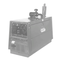
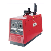
The Lincoln Electric Shield-Arc 500AS (KA1353) is an engine-powered arc welding machine designed for industrial and professional use. This robust welder is equipped with a Perkins 4/236 Diesel engine and features dual continuous control of the welding output, allowing for precise adjustment of both voltage and current to suit various welding applications.
The primary function of the Shield-Arc 500AS is arc welding, providing a direct current (DC) output ranging from 60 to 600 amps. It is designed to deliver consistent welding performance, even under severe operating conditions. The machine also offers auxiliary AC power outlets (240 volt, 10 amp and 115 volt, 3 pin) for powering tools or lighting, and can be used as a temporary stand-by power unit.
The welder's output is controlled by two main adjustments: the Job Selector and the Continuous Current Control. The Job Selector provides a coarse adjustment of the open circuit voltage and acts as a fine current adjustment. It is divided into four sections: "Large Electrodes" for high open circuit voltage, "Normal Welding Range" for medium-high open circuit voltage, "Overhead and Vertical" for medium-low open circuit voltage, and "Special Applications" for a low open circuit voltage, used with a minimum setting on the Continuous Current Control. The Continuous Current Control provides the major adjustment of welding current, with a dial that reads continuously in a clockwise direction from maximum to minimum. When the Job Selector is set to "Overhead and Vertical," the approximate welding current is indicated on the corresponding scale of the Current Control dial. This dual control system allows for flexibility in achieving the desired arc characteristics for different welding techniques and electrode types.
The machine is also equipped with safety features to protect both the operator and the equipment. These include a key switch for starting and stopping the engine, and various internal components designed for safe electrical operation.
Before starting the welder, operators must ensure the engine's oil level is at the "Full" mark, the radiator is filled with a 50-50 mixture of water and glycol (if operating near or below zero temperatures), and the fuel tank is filled with clean fuel. The dry-charged battery must be filled with electrolyte and boost charged according to specific instructions. For new engines or those that have been idle for a long time, the fuel system needs to be bled.
To start the welder, the start switch is turned to the "H" position for 15-20 seconds, then further clockwise to the "start" position. Once the engine starts, the switch must be released to return to the "on" position. Operators are cautioned not to turn the start switch to "start" while the engine is running to avoid circuit or component damage. If the engine is warm and has been stopped for a short period, it can be restarted by turning the start switch directly to the "start" position. The "H" position is a definite spring-loaded location between "on" and "start." If the oil pressure gauge does not show normal oil pressure within 10 seconds of starting, the engine should be stopped, and the engine instruction manual consulted.
Before drawing welding current, the polarity switch must be set to either "Electrode +" or "Electrode -" position, depending on the electrode type and welding application. The engine speed is factory pre-set for optimum welder performance and should not be altered, as doing so will void the warranty. To stop the engine, the key switch is turned to the "off" position.
When setting controls for welding, for example, a vertical up weld with a 4.0mm electrode at 135 amps, the Job Selector should be set to "Overhead and Vertical," and the Current Control to 135 amps on the "Overhead and Vertical" scale. If the arc is too weak, the Job Selector can be moved counter-clockwise to increase current, or the Current Control can be turned up. It is crucial to keep the Job Selector within the correct range for the desired arc characteristics.
For auxiliary power, the machine provides two 240 volt, 10 amp outlets and two 115 volt, 3 pin outlets. Both can be used simultaneously, provided the total current draw does not exceed 16.5 amps or 4,000 watts. The auxiliary power circuits are not connected to the welder frame, and earth leakage protection is not required, but connected equipment should be double insulated or fitted with an effective earth wire. If a Residual Current Device (RCD) is fitted, the machine frame must be earthed in accordance with AS3000, Clause 5.6.
Routine maintenance is crucial for the longevity and safe operation of the Shield-Arc 500AS. Operators should consult the engine manufacturer's operating manual for detailed engine maintenance and troubleshooting. Key engine maintenance tasks include changing crankcase oil and oil filters at regular intervals, checking and tightening fan belts after the first 30-40 hours of operation, and pulling down cylinder head nuts after 25 hours of operation. It is important not to over-tighten fan belts.
For the welder components, all nuts and bolts should be checked for tightness after 25 hours of initial use, and then every 1000 hours thereafter. The welder and controls should be blown out with an air hose at least once every two months, or more frequently in dirty environments, using low-pressure air to avoid driving dirt into the insulation. Current Control reactor brushes, made of silver graphite, should not be greased, and contacts should be kept clean. Electrode and work connections must be kept tight.
The welder is equipped with double-shield ball bearings that are pre-greased for indefinite use under normal conditions. However, in constant use or excessively dirty locations, 15 grams of grease should be added annually. When greasing, it is vital to keep dirt out of the area by wiping the fitting clean and using clean grease and equipment.
Commutator and brushes require periodic inspection. The generator and alternator brushes are factory-adjusted and should not be shifted. If the commutator or slip rings appear black or uneven, an experienced maintenance person should clean them with fine sandpaper or a commutator stone, never emery cloth or paper. Brushes should be replaced when they wear within 6mm of the pigtail, and a complete set of replacement brushes should be kept on hand. When fitting new brushes, the pigtail should be twisted to ensure it is tightly packed and does not protrude beyond the brush surface, allowing for free radial movement. New slip ring brushes should be sanded to seat them properly, and slip rings should be stoned with a 320 grit sanding stone, then cleaned of oil and grease. Lincoln generator brushes have a curved face and should be seated by lightly stoning the commutator as the armature rotates at full speed until full contact is made. Dust should be blown out with low-pressure air after stoning.
Battery maintenance involves keeping electrolyte levels about 6mm above the plates and separators, keeping terminal posts free of corrosion, and keeping the battery clean and dry. The machine should not be left switched on without the engine running, as this will discharge the battery. Fast charging should not be done on batteries over 18 months old, and acid should only be added to a battery if replacing acid lost through spillage.
A ground test procedure is outlined for use with DC mega testers up to 500V. This involves ensuring the engine is stopped, disconnecting welding leads, auxiliary equipment cables, and battery leads. Leads from the battery charge alternator and battery charger PCB should be removed and connected together. Volt/amp meter terminals and hour meter terminals should be jumpered together. Earth leads from the bridge rectifier, water temperature gauge and sender, voltmeter, stop solenoid, hour meter, engine watcher warning light, and RCD should be removed. The current control and voltage rheostat should be set to maximum, and the reversing switch to "electrode positive." The key switch and start/run switch should be in the "run" position, and the auxiliary switch to "on." The thermostat lead from terminal No. 5 on the key switch should be removed. Various components, including bridge rectifiers, slip ring brush pig tails, 240V auxiliary outlets, and positive output stud, are then tested for insulation resistance (minimum 1MΩ or 10MΩ depending on the circuit). All jumper leads and disconnected leads must be reconnected after the procedure.
The manual also provides detailed troubleshooting steps for common issues such as the machine failing to start, starting but having no voltage or reduced voltage at welder output studs or AC outlets, and low welding output or inability to hold welding current constantly. These steps guide the operator or technician through checking various components and connections, offering solutions like replacing faulty parts, cleaning contacts, or realigning components.
| Frequency | 50/60 Hz |
|---|---|
| Rated Output | 500 A AC/DC, 40 V, 60% Duty Cycle |
| Phase | 3 |
| Weight | 550 lbs (249 kg) |
| Dimensions (H x W x D) | 39 x 27 x 47 in (991 x 686 x 1194 mm) |