EasyManua.ls Logo

Lincoln Electric Shield-Arc SAM400 User Manual

Lincoln Electric Shield-Arc SAM400
32 pages
To Next Page IconTo Next Page
Page #1 background imageLoading...
Page #1 background image
IMA 523D
OPERATING MANUAL
SHIELD-ARC
®
SAM-400
KA 1355
SAFETY DEPENDS ON YOU
Lincoln welders are designed and built with safety in mind. However, your overall safety can be increased
by proper installation . . . and thoughtful operation on your part. Read and observe the general safety
precautions on page 2 and follow specific installation and operating instructions included in this manual.
Most importantly, think before you act and be careful.
THE LINCOLN ELECTRIC COMPANY
(A
US
TRALIA) PT
Y
.LTD.
A.C.N. 000 040 308
SYDNEY
.
A
USTRALIA
A Subsidiary of
THE LINCOLN ELECTRIC CO. U.S.A.
Associated Subsidiaries in Australia, Europe, Asia, North and South America.
THE
W
ORLD'S LEADER IN
WELDING AND CUTTING PRODUCTS
Question and Answer IconNeed help?

Do you have a question about the Lincoln Electric Shield-Arc SAM400 and is the answer not in the manual?

Lincoln Electric Shield-Arc SAM400 Specifications

General IconGeneral
BrandLincoln Electric
ModelShield-Arc SAM400
CategoryWelding System
LanguageEnglish

Summary

OPERATING MANUAL

ARC WELDING SAFETY PRECAUTIONS

ELECTRIC SHOCK can kill

Detailed safety warnings regarding electric shock hazards during arc welding.

FUMES AND GASES can be dangerous

Safety precautions related to hazardous fumes and gases produced during welding.

ARC RAYS can burn

Guidelines for protecting eyes and skin from arc rays and spatter.

WELDING SPARKS can cause fire or explosion

Precautions to prevent fires and explosions caused by welding sparks.

CYLINDER SAFETY

SAFETY FOR COMPRESSED GAS CYLINDERS

Safety instructions for handling compressed gas cylinders used in welding.

EQUIPMENT POWER SAFETY

ELECTRICALLY POWERED EQUIPMENT SAFETY

Safety guidelines for equipment powered by electricity.

ENGINE POWERED EQUIPMENT SAFETY

Safety precautions for operating engine-powered equipment.

HOW TO ORDER REPLACEMENT PARTS

WELDING EMF AND PACEMAKERS

MINIMISING EMF EXPOSURE

Procedures to reduce exposure to electric and magnetic fields (EMF).

WELDER PACEMAKER SAFETY

Specific safety advice for welders with pacemakers.

ELECTROMAGNETIC COMPATIBILITY

ASSESSMENT OF AREA FOR EMC

Evaluating the surrounding area for potential electromagnetic problems.

METHODS OF REDUCING EMC EMISSIONS

Techniques to minimize electromagnetic interference from welding equipment.

SPECIFICATIONS AND OPERATING INSTRUCTIONS

ENGINE SPECIFICATIONS

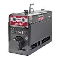
Technical details of the engine used in the welder.

WELDER SPECIFICATIONS

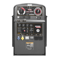
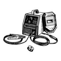
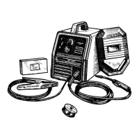
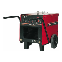
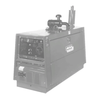
Technical details of the welding machine itself.

ENGINE OPERATION AND MAINTENANCE

Guidance on operating and maintaining the engine.

BEFORE STARTING THE ENGINE

Pre-operation checks and procedures before starting the engine.

WELDING OPERATION AND OUTPUT

OUTPUT CHARACTERISTICS

Description of the machine's constant and variable voltage outputs.

WELDER CONNECTION AND OPERATION

Instructions for connecting and operating the welder for various processes.

CONTROL SETTINGS

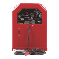
Explains the various controls and their settings for welding operations.

AUXILIARY POWER

Information on the auxiliary power outlets and their usage.

WELDING CONTROLS AND SETTINGS

USE OF WELDERS AS STAND-BY POWER UNITS

Guidelines for using the welder as a backup power source.

OUTPUT STUDS AND TOGGLE SWITCH

Details on output stud connections and the toggle switch function.

ELECTRODE POLARITY AND RANGE SELECTOR

Instructions for setting electrode polarity and voltage range.

CURRENT AND VOLTAGE CONTROLS

How to use current and voltage controls for different welding modes.

BATTERY AND WELDER MAINTENANCE

BATTERY FILLING AND SERVICE INSTRUCTIONS

Procedures for filling, servicing, and maintaining the battery.

INSTALLATION AND BATTERY MAINTENANCE

Steps for installing the battery and ongoing maintenance.

WELDER MAINTENANCE

General maintenance procedures for the welding machine.

ROUTINE MAINTENANCE AND BEARINGS

Scheduled maintenance tasks and bearing lubrication.

GROUND TEST PROCEDURE AND MAINTENANCE

GROUND TEST PROCEDURE

Step-by-step guide for performing ground tests on the machine.

CONTACTOR MAINTENANCE

Instructions for inspecting and maintaining the output contactor.

WIRE FEEDER CONNECTIONS

LN7 AND LN21 WIRE FEEDER CONNECTIONS

Wiring diagrams and connection notes for LN7 and LN21 feeders.

LN23P WIRE FEEDER CONNECTIONS

Wiring diagrams and control settings for the LN23P feeder.

LN22 WIRE FEEDER CONNECTIONS

Wiring diagrams and connection notes for LN22 feeders.

WIRE FEEDER OPERATION AND CONNECTIONS

LN8 AND LN9 WIRE FEEDER CONNECTIONS

Connection details for LN8 and LN9 wire feeders.

LN21 OPERATION AND CONNECTIONS

Operating and connection guide for the LN21 wire feeder.

LN22 OPERATION AND CONNECTIONS

Operating and connection guide for the LN22 wire feeder.

STICK ELECTRODE WELDING SETTINGS

STICK ELECTRODE WELDING (VARIABLE VOLTAGE)

Detailed settings for stick welding using variable voltage.

STICK ELECTRODE WELDING (VARIABLE VOLTAGE - INNERSHIELD)

Settings for Innershield with variable voltage for fast travel speeds.

OPEN ARC WELDING MODES

INNERSHIELD AND OTHER OPEN ARC WELDING (CONSTANT VOLTAGE)

Settings for Innershield and other open arc welding using constant voltage.

LOW VOLTAGE - LOW CURRENT OPEN ARC WELDING (CONSTANT VOLTAGE WITH VARIABLE INDUCTANCE CONTROL)

Settings for low voltage/current open arc welding with variable inductance.

TROUBLESHOOTING GUIDE

LOSS OF OUTPUT IN ONE MODE ONLY

Troubleshooting steps for output loss in a single welding mode.

LOSS OF OUTPUT IN BOTH MODES OF OPERATION

Diagnosing and resolving output loss in both constant and variable modes.

NO CONTROL OF OUTPUT

Troubleshooting steps when there is no control over the welding output.

TROUBLESHOOTING CONTINUED

OUTPUT LOW IN BOTH MODES - OPEN CIRCUIT VOLTAGE LOW

Addressing low open circuit voltage in both CV and VV modes.

ARC DIFFICULT TO START IN CV POSITION USING LOW CURRENT AND VOLTAGE

Solutions for difficult arc starting in CV with low current/voltage.

P.C.B. CALIBRATION

P.C.B. CALIBRATION (VARIABLE VOLTAGE)

Calibration procedure for the PCB in variable voltage mode.

P.C.B. CALIBRATION (CONSTANT VOLTAGE)

Calibration procedure for the PCB in constant voltage mode.

WIRING DIAGRAM

SCHEMATIC DIAGRAM

GENERAL ASSEMBLY (AP-27-C)

ASSEMBLY COMPONENTS

ELECTRONIC COMPONENT PANEL ASSEMBLY (AP-36-E.1)

CONTROL PANEL & OUTPUT STUD ASSEMBLY (AP-36-D)

ALTERNATOR ASSEMBLY COMPONENTS

WELDING GENERATOR AND COUPLING (AP-27-F)

FRAME, FUEL, TANK AND REACTOR (AP-33-E)

GENERATOR BRUSH HOLDER (AP-9-G)

PORTABLE FIELD CONTROL (AP-27-J)

Instructions and parts for the portable field control unit.

S-78 STARTER (AP-27-L)

UNDERCARRIAGE (2-WHEEL TYPE) (AP-22-A)

UNDERCARRIAGE (4-WHEEL TYPE) (AP-89)

WARRANTY

WARRANTY PERIOD AND CONDITIONS

Details on the warranty period, terms, and conditions.

SPARE PARTS POLICY

Information regarding the availability of spare parts.

Related product manuals