Do you have a question about the Lincoln Electric spirit II 150 and is the answer not in the manual?
| Brand | Lincoln Electric |
|---|---|
| Model | spirit II 150 |
| Category | Welding System |
| Language | English |
Essential safety guidelines for operator and equipment.
Measures to protect against ultraviolet radiation exposure.
Recommendations for hearing protection due to system noise levels.
Safety protocols for ventilation and fume management.
Critical safety measures to prevent electrical hazards during operation.
Procedures to mitigate fire risks from sparks and flammable materials.
Guidelines for handling compressed gases safely to prevent explosions.
Safety considerations for individuals with medical devices like pacemakers.
List of external publications for further safety information.
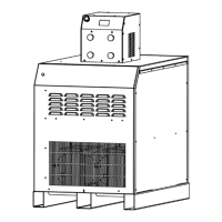
Overview of the Spirit II system's capabilities and design.
Identification of standard and optional system components.
Detailed electrical and physical specifications of the power supply.
Requirements and details for the torch cooling system.
Technical details for the automatic gas control unit.
Specifications for plasma, shield, preflow, and marking gases.
Physical and interface specifications for the plasma console.
Technical details for ASC with RHF and CleanStrike options.
Dimensions and part numbers for torch and manifold assemblies.
Physical specifications for the 5-gang manifold assembly.
Data on noise levels generated by the system during operation.
Information regarding the system's EMC compliance.
Steps for inspecting components and choosing installation locations.
Diagrams illustrating system component connections.
Detailed instructions for connecting primary power to the unit.
Guide for connecting power supply outputs to ASC and work table.
Procedures for connecting ASC cables and cooling system hoses.
Instructions for connecting torch leads and gas hoses.
Connecting external gas supply lines to the Automatic Gas Console.
Connecting the plasma console and communication interfaces.
Interface requirements for connecting to CNC cutting machines.
Step-by-step guide for filling and priming the coolant system.
Navigating and using the plasma console touch screen interface.
Process for selecting material, thickness, and cut/mark parameters.
Checking system settings and identifying required torch consumables.
Interpreting system status indicators for operational readiness.
Procedure for adjusting and setting gas pressures via the console.
Sequence of operations for initiating and performing a cut or mark.
Techniques for safely piercing thick materials without component damage.
Guidelines for achieving optimal cut quality and adjusting parameters.
Creating, saving, and managing custom cutting or marking setups.
Exploring system settings like RS422, Hydrogen Cutting, and Language.
Using diagnostic tabs for system monitoring and error analysis.
Step-by-step guide for attaching and detaching the torch head.
Procedures for replacing worn or damaged torch consumables.
Tips and guidelines to extend the lifespan of torch parts.
Visual checks for wear and damage on consumable parts.
Charts detailing correct consumables for different materials and amperages.
Reference tables providing starting parameters for various cutting tasks.
Regular checks and cleaning for optimal system performance.
Procedure for flushing and replacing the coolant and filter cartridge.
Understanding power supply indicators and their operational sequences.
Identifying system errors and common troubleshooting steps.
Detailed steps for testing the power supply chopper module.
List and location of parts within the power supply unit.
Parts list for automatic gas, plasma, and arc starting consoles.
List of parts for torch handles, bases, heads, and manifolds.
Inventory of various cables, hoses, and connecting leads.
Reference diagrams for PCB components in the power supply.
Introduction to the Inova option and its connection points.
Grounding requirements and specific cables for the Inova system.
List of components for the internal Inova console.
Information on EMC standards and proper installation practices.
Techniques to minimize electromagnetic interference.
Steps for initializing the system and sending parameters via serial port.
Methods for verifying communication integrity and identifying errors.
Detailed reference of RS-422 commands for system control.