3
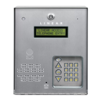
220793 F IMAGE 3
Feature Overview
Relay Outputs
Two 3-amp dry contact relay outputs are provided to activate access devices, such
as door strikes, magnetic locks, automatic doors, barrier gates, and automatic
sliding gates. One relay output can also be used as a specialty output for alarm
contact shunting, operator obstacle triggering, and alarm activation. LED indicators
display the status of each relay.
Request-to-Exit Inputs
Both relay channels have request-to-exit inputs. These inputs are supplied for
hardwire activation of the access devices. Typically a request-to-exit input is wired
to a pushbutton inside of the access controlled area. When a person desires to
exit, pressing the pushbutton will activate the output relay channel and trigger the
access device. A loop detector for automatic gate operation can be connected to
a request-to-exit input.
Sensing Input
The sensing input connects to a door switch that monitors whether the controlled
door is open or closed. The sensing input may alternately be programmed as an
“access inhibit” input for use with an external access timer or service switch.
Built-in Modem
A modular connector is provided for telephone line connection to the unit’s built-in
14.4K baud modem. The system can be accessed remotely for programming and
control over the standard telephone system using a personal computer with a
modem. For system backup, a computer connected through the modem can store
and retrieve the AM-500’s memory data.
Local Keypad
The local keypad is the system’s primary keypad. The local keypad will activate
Relay Channel “A”.
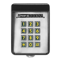
Remote Keypad
Two models of remote keypads (interior Linear AM-KPI and exterior Linear
Model AM-KP) are compatible with the AE-500. A typical application for a remote
keypad would be to control a second door or gate. A remote keypad will activate
Relay Channel “B” only. Relay Channel “A” can only be controlled by the AE-500
keypad.
Postal Lock
The AE-500 cabinet has provisions for installing a U.S.P.S. postal lock for keyed
mail carrier access. The postal lock will activate Relay Channel “A”.
Color Camera
The AE-500 cabinet has provisions for installing a Linear Model CCM-1 color
camera for viewing the area in front of the cabinet.
Obstacle Detection
Linear’s Model MGT safety edge transmitter is compatible with the AE-500. The
MGT detects and transmits obstacle events to the AE-500. Obstacle signals from
a MGT transmitter will activate Relay Channel “B”.
Programming Memory
The AE-500’s EEPROM memory retains all entry codes, transmitter information,
and programming, even without power.
Web-style Computer Programming
The system’s built-in, web-style programming interface can be accessed using a
computer with any Internet browser on-site (using a separate phone line) or off-
site. The intuitive graphic display of each of the programming step is the preferred
method to program the AE-500.
Local Programming
All system programming options can be set from the AE-500’s keypad. A computer
or dedicated programmer is not required to completely confi gure the AE-500.
Telephone Programming
System programming options can be set using a standard TouchTone™ telephone.
By calling the AE-500 from a telephone, and entering the programming password,
programming options can be changed and system functions can be controlled.
Battery Backup
The system supports a 12-volt battery backup for operation during power outage.
The system does not charge the backup battery, an external battery charger is
required to maintain the battery.
Database Overview
Programming the AE-500 involves entering installation information into
the system’s memory. The system uses this information as a reference
“database” to control the operation of the system.
Resident Data
Up to 250 resident names and telephone numbers can be set. Each
resident entry is assigned a directory number. Directory numbers can be
from two to four digits in length (all will be the same length). The directory
number is the number a visitor would enter to have the system call the
resident.
Entry Code Data
Up to 500 entry codes can be set. Entry codes can be from two to six
digits in length (all will be the same length). An entry code is a number
entered at the local or remote keypad to request access. The entry code
will activate Relay Channel “A” or “B” depending on which keypad the
code is entered on. The AE-500 keypad controls Channel “A” Relay, the
remote keypad controls Channel “B” Relay. Each entry code can be set
to restrict which relay activates. Entry codes can also be set to toggle the
relay output (output latches on until the next time a toggle entry code is
entered). Each entry code can be set for a limited or unlimited number
of uses.
Transmitter Data
Up to 1000 wireless transmitters can be used with the system. Up to 500
transmitters can be ordered in pre-programmed blocks of sequential ID
codes. Up to 16 blocks of transmitters can be used. Another option is
to utilize up to 500 transmitters that are singly assigned. A transmitter
will activate either relay output depending on the button programming
(same for all transmitters in the system). An individual transmitter can be
deactivated in case it is lost or stolen. A single enrolled transmitter can
also be deleted.
RESIDENT DATA (UP TO 250 RESIDENTS)
DIRECTORY NUMBER (2 TO 4 DIGITS)
NAME (UP TO 16 CHARACTERS)
PHONE # (UP TO 12 DIGITS)
FOR EACH RESIDENT:
ENTRY CODE DATA (UP TO 500 CODES)
ENTRY CODE (2 TO 6 DIGITS)
RELAY SELECTOR
TEMPORARY USAGE COUNT
FOR EACH CODE:
TRANSMITTER DATA (UP TO 1000 TRANSMITTERS)
TRANSMITTER ID # (1-65535)
OPTIONAL FACILITY CODE (0-15)
FOR EACH TRANSMITTER: