Rev: 10.05.18
Page 6
CCD-0001632
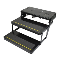
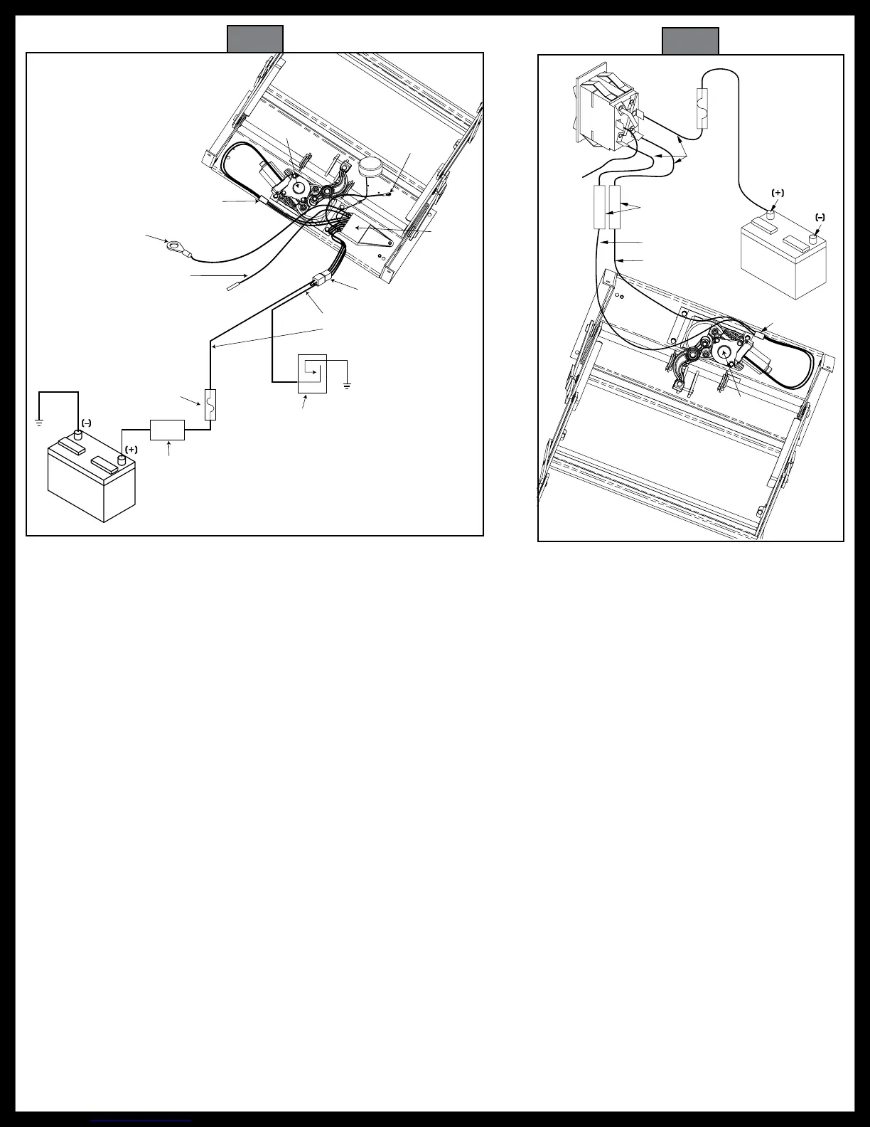
Fig. 2
Vehicle Wiring
Step Wiring
Four-way
connector
16 AWG brown
12 AWG red
Chassis ground
Normally OPEN
magnetic door switch
20-25 amp fuse or
curcuit breaker required
Battery
disconnect
box/switch
IMPORTANT:
If the switch is
'OFF' the step
will not
operate.
Chassis
ground
12 volt DC
battery
16 AWG purple
optional step light switch
may be connected to porch
light switch (see Inset 10A)
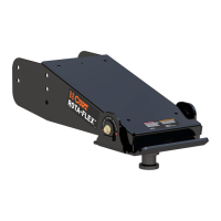
Motor
assembly
Understep light
(not available on
all step models)
12 AWG green
ground to step top
Control unit
(black)
Two-way
connector
12 AWG green ground wire
must be securely attached to
the chassis for step to operate
12
volt DC
battery
Rocker
Switch
16 gauge red
16 gauge yellow
10 gauge to
chassis ground
25 amp
in-line
fuse
Automotive connectors
(not supplied)
10 gauge
minimum
Motor
assembly
Two-way
connector
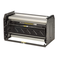
Fig. 3
3. Disconnect the 4-way connector on the underside of the step and connect the step-half of the
connector with the 4-way connector pigtail (Fig. 1, Fig. 2 and Fig. 3).
4. Set a fully charged 12 volts DC automotive battery beside the step.
NOTE: Do not allow the battery terminals to come in contact with step. Complete a ground for step testing
by connecting 10 AWG wire from the negative battery terminal to the green ground wire of the
control unit.
5. For the power supply, attach the red wire from the pigtail to the positive battery terminal.
6. With the power and ground connections complete, all functions of the control unit can be checked at
the four wires of the pigtail. The brown wire is the door switch, the white wire is the power switch, and
the yellow wire is the ignition override.
7. To extend the step, touch the white wire to the positive battery terminal. The step should extend and
remain extended.
8. To retract the step, hold the white wire to the positive battery terminal and touch the brown wire to
the negative battery terminal.
9. To test the Ignition Override feature, extend the step. With the step extended, disconnect the white
wire from the battery and attach the brown wire to the battery's negative battery terminal. Next, touch
the yellow wire to the positive battery terminal. The step should retract. Remove the brown wire and
the step should extend.
To test the "Last Out" feature, touch the brown wire to the negative battery terminal to retract the step. While
holding the brown wire to the negative battery terminal, remove the yellow from the positive battery terminal. The
step will stay retracted. Now, remove the brown wire. The step should extend.
10. If any of the step functions do not work, the source of the malfunction is either in the control unit and/
or the motor. Proceed to the "Testing the Motor" section.
If all of the step functions do work, the malfunction is either in the door switch, power switch, or the vehicle wiring.
Proceed to "Testing the 4-way Connector" section.
 Loading...