Rev: 10.05.18
Page 7
CCD-0001632
Disconnect The 2-Way Connector Between The Step Motor And The Control Unit
1. Connect the red motor wire to the positive battery terminal and touch the yellow motor wire to the
negative battery terminal to extend the step. To retract the step, reverse the connections. If the step
extends and retracts during this test, the condition of the step motor is good. To retract the step,
reverse the connections. If the step extends and retracts during this test, the condition of the step
motor is good.
NOTE: On steps with reverse polarity plug Part Number 1800711 (Kwikee®) or Part Number 365884 (LCI®)
reverse the red and yellow wire connections to perform the previous test.
Testing The Motor
Voltmeter should read
0 volts DC / step
switch Automatic Mode or
12 volts DC / step
switch Lock Position.
White
4-way connector
(vehicle-side)
Ground wire: green ground wire
must be attached to vehicle
chassis; a good ground is needed
for proper step operatio
Fig. 5
Voltmeter should read
12 volts DC when door
is closed
Voltmeter should read
0 volts DC when door
is open
4-way connector
(vehicle-side)
Red
Brow
n
Fig. 6
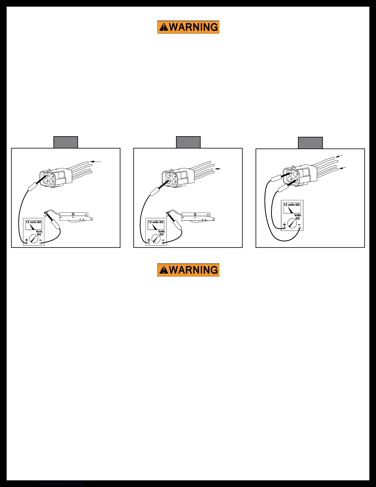
Fig. 4
Red
4-way connector
(vehicle-side)
Ground wire: green ground wire
must be attached to vehicle
chassis; a good ground is needed
for proper step operation
Voltmeter should
read 12 volts DC
1. To check the main power source, connect a voltmeter between the red wire from the 4-way connector
(vehicle half) and the ground terminal at the end of the control unit’s green ground wire (Fig. 4). The
reading should be a minimum of 12 volts DC.
If the voltage reading is low, there may be a loose or corroded connection at the battery, a low charge level on the
battery itself, or a poor ground. If the voltage reading is 0 volts, check the step fuse/circuit breaker, all connections,
and the condition of the wiring between the battery and the plug, including the ground connection at the chassis.
2. To check the override switch, connect a voltmeter between the white wire from the 4-way connector
(vehicle half) and the terminal at the end of the control unit green ground wire (Fig. 5). The reading
should be a minimum of 12 volts DC when the switch is on, and 0 volts DC when the switch is off.
If the voltmeter reads 0 volts when the override switch is on, there is a problem in the override switch circuit. Check
the 6 amp in-line fuse, the override switch itself and the condition of the circuit wiring and terminal connections.
3. To check the door switch, connect a voltmeter between the red wire from the 4-way connector (vehicle
half) and the brown in the same connector (Fig. 6). The voltage should be a minimum of 12 volts DC
when the door is closed and 0 volts DC when the door is open.
Testing The 4-Way Connector
Do not leave the wires connected during this test once the step has cycled either in or out. Failure to
remove the wires from the battery will burn out the motor voiding any warranty.
Do not leave the wires connected during this test once the step has cycled either in or out. Failure to
remove the wires from the battery will burn out the motor voiding any warranty.

 Loading...