Rev: 09.11.19 Page 2
CCD-0002616
TABLE OF CONTENTS
Introduction 2
Safety 2
Resources Required 3
Installation 3
Wiring Diagram For 5
Step with Control Unit 5
Wiring Diagram For Optional Porch Light 5
Operation 6
Step with Control Unit 6
Troubleshooting 7
Introduction
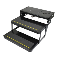
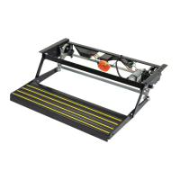
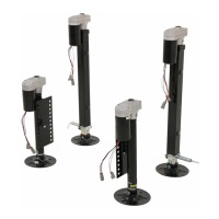
This manual provides instructions for installation of Kwikee® Electric Steps, which are equipped with a step
lockout switch, control unit and permanent magnet motor onto a motorized coach. This manual does not
apply and should not be used as a reference to previous versions of a Kwikee® Electric Step.
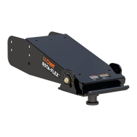
The control unit is a current sensor as well as a switching device. When the motor assembly moves the step
tread to its extended position, or stops moving because of an obstruction such as a curb or the binding of a
damaged or bent step frame, the motor draws a larger amount of current. The control unit senses the larger
current draw and shuts off the power to the motor.
Control units are equipped with an ignition override system. This system is designed so the vehicle will
not be driven with the step in the extended position. When the step is locked in the extended position,
the door closed, and the ignition is turned on, the ignition override system will engage and the step will
automatically retract.
The Auto Extend feature is another safety feature designed to extend the step when the door is opened for
the first time after the vehicle ignition is turned off, regardless of the position of the step switch.
Safety
Read and study the manual before operating the steps. Adhere to all safety labels.
This manual provides general instructions. Many variables can change the circumstances of the instructions,
i.e., the degree of difficulty, operation and ability of the individual performing the instructions. This
manual cannot begin to plot out instructions for every possibility, but provides the general instructions,
as necessary, for effectively interfacing with the device, product or system. Failure to correctly follow the
provided instructions may result in death, serious personal injury, severe product and/or property damage.
The “WARNING” symbol above is a sign that a procedure has a safety risk involved and may cause
death or serious personal injury if not performed safely and within the parameters set forth in
this manual.
Failure to follow instructions provided in this manual may result in death, serious personal injury
and/or severe product and property damage, including voiding of the component warranty.
The “CAUTION” symbol above is a sign that a safety risk is involved and may cause personal injury
and/or product or property damage if not safely adhered to and within the parameters set forth
in this manual.