5
lippert.com 432-LIPPERT (432-547-7378) Rev. 09.29.23
JT’s Strong Arm
™
Installation and Owner’s Manual
(For Aftermarket Applications)
CCD-0001455
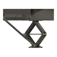
Option 1 - Fig. 1
1. Mark the bottom of the center compartment centered
between the front electric jacks. Mark the center of one of
A.
pad ¼” from the front edge of the center compartment.
B.
pad on the bottom of the center compartment and center-
punch the marks.
Fig.1
REMOVE PERSONAL PROPERTY AND VALUABLES
FROM THE CENTER COMPARTMENT TO PREVENT
POSSIBLE DAMAGE OCCURRING DURING
DRILLING.
C. To prevent accidental damage to personal property,
clear the center compartment of any valuables.
D. ⁄” pilot hole at each mounting hole location.
E. ⁄” mounting holes. Use a countersink bit to deburr
the inside of the holes.
F.
I. Insert two ⁄” - 16 x 1 ¼” swing bolts and secure with
two ⁄”⁄” - 16 nylon locking nuts.
II. Tighten nuts enough to ensure needing a screwdriver
for leverage to pivot swing bolts.
2. Go to Front To Rear Bracket Installation.
Option 2 - Fig. 1
1. Mark the bottom of the cross-member centered between
between the mounting holes.
A.
bottom of the cross-member, clamp pads with a pair of
locking pliers or C-Clamps.
B.
⁄” mounting holes. Use a countersink bit to
deburr inside of holes.
C.
I. Insert two ⁄” - 16 x 1 ¼” swing bolts, and secure with
⁄”⁄” - 16 nylon locking nuts.
II. Tighten nuts enough to ensure needing a screwdriver
for leverage to pivot swing bolts.
2. Go to Front To Rear Bracket Installation.
Option 3 - Fig. 2
1. From the inside of one of the front jacks, measure
toward the center of the cross-member 30” and place a
mark.
A.
mounting holes.
B.
bottom of the cross-member and clamp with a pair of
locking pliers or C-Clamp.
C. ⁄” bit.
D.
cross-member with a ⁄” x 1 ¼” swing-bolt, a ⁄” x 1 ½”
bolt, ⁄” washers, and ⁄” - 16 nylon locking nuts.
NOTE: The swing bolt should be inserted into the mounting
hole located closest to the jack.
Fig.2

 Loading...