8
lippert.com 432-LIPPERT (432-547-7378) Rev. 09.29.23
JT’s Strong Arm
™
Installation and Owner’s Manual
(For Aftermarket Applications)
CCD-0001455
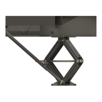
Fig.7
Fig.6
Jack Clevis Assembly - Fig. 6
1. Make sure the adjustment holes in each jack leg above
the foot pad pin are ½” diameter. If not, re-drill hole with
a step bit or standard ½” bit, then deburr holes with a
countersink bit.
A. Insert a ⁄”½”
second from the bottom holes in each jack leg.
B. Apply a thin layer of white grease to the shaft of a
⁄”
C. For each jack leg, do as follows:
I. Align the mounting holes of the electric jack clevis
with the bushings from the rear of the jack leg and insert
the swing bolt through both sides with the shoulder and
⁄” washer on the inside of the jack leg.
II. Apply a thin layer of grease to a ⁄” washer and place
on outside of clevis, over the swing bolt.
III. Secure the swing bolt and clevis with a ⁄” - 16
grade A heavy hex nut.
IV. Tighten heavy hex nut enough to eliminate side
play.
D. Thread a ⁄” - 16 nut (“Silver Bullet”) lifting handle onto
the outside of the swing bolt. Tighten lifting handle nut
against the ⁄” - 16 heavy hex nut.
Front to Rear Stabilizer Assembly
Stabilizer Tube Assembly - Fig. 7
1. Apply white grease to the threads of a T-Bolt, then
partially thread it into the top hole of the outer stabilizer
tubes.
A. Remove inner stabilizer tube from assembly and
discard the plastic shipping bag.
B. Reassemble stabilizer tubes with the inner tube
sticking out past the end of the outer tube by 5”. Tighten
T-Bolts until snug.
2. To ensure proper installation, make sure the warning
labels are facing outward and right-side up. The T-Bolts
should be on the top side of the stabilizers.
A. Apply a thin layer of white grease to swing bolt tabs.
B. Attach clevis end of outer stabilizer tube to the swing
bolt tab under center of chassis with a
⁄” - 16 x 1 ½”
bolt, ⁄” washer and ⁄” - 16 nylon locking nut.
C. Tighten nut until the stabilizer tubes swing to the
ground with resistance.
D. Attach clevis end of inner stabilizer tube to swing bolt
tab on jack leg with a ⁄” - 16 x 1 ½” bolt, ⁄” washer and
⁄” - 16 nylon locking nut. Loosen T-Bolt if needed.
E.

 Loading...