7
lippert.com 432-LIPPERT (432-547-7378) Rev. 09.29.23
JT’s Strong Arm
™
Installation and Owner’s Manual
(For Aftermarket Applications)
CCD-0001455
Fig.5
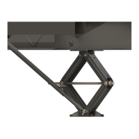
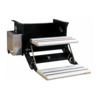
Fig.4
Front to Rear Bracket Installation
NOTE: For chassis that are constructed with “I” or “H”
beam main rails (front-to-rear) and are uninsulated, go to
Option 1. For chassis that are constructed with “I” or “H”
beam main rails or tubular frames and/or insulated, go to
Option 2.
Option 1 - Fig. 4
1. From the rear side of an electric jack leg, measure 30”
and place a mark on the bottom of each main rail. Measure
measurement by four to determine the center location of
the mounting hole.
A. Center punch the intersection of the lines, then drill a
⁄” pilot hole.
B. Re-drill out the pilot hole to ⁄” and deburr with a
countersink bit.
C.
⁄” - 16 x 1 ¼” swing bolt, a ⁄” washer and
a ⁄” - 16 nylon locking nut.
NOTE:
D. ⁄” -
16 x 1 ½” bolt, ⁄” washer and ⁄” - 16 nylon locking nut.
E.
Option 2 - Fig. 5
1. Measure from the rear side of the electric jack leg
Assemble a spacer mount.
A. Using the spacer mount as a template, mark the
mounting holes by aligning one short edge with the
NOTE: The spacer mount should be parallel to the outside
B. Center punch and drill ⁄” pilot holes at each mounting
hole location.
C. Re-drill the holes located closest to the front jacks to
⁄” on both sides of the chassis.
D. Tap the ⁄” holes with either a ⁄” - 16 tap or a ⁄” - 16
x 1” self-tapping bolt. Lubricate tap as needed.
E.
with a ⁄” - 16 x 1” self-tapping bolt, taking care to keep
the remaining pilot hole centered in the mounting of the
spacer mount. Tighten bolt securely.
F. Re-drill the remaining pilot hole to ⁄”. Then insert a
⁄” - 16 x 1” self-tapping bolt and tighten.
G. Repeat steps 1-1F for opposite side of the chassis.

 Loading...