9
lippert.com 432-LIPPERT (432-547-7378) Rev. 09.29.23
JT’s Strong Arm
™
Installation and Owner’s Manual
(For Aftermarket Applications)
CCD-0001455
Side to Side Stabilizer Assembly - Fig. 8 & 9
1. Apply white grease to the threads of a T-Bolt, then
partially thread it into the top hole of the outer stabilizer
tubes.
A. Remove inner stabilizer tube from assembly and
discard the plastic shipping bag.
B. Reassemble stabilizer tubes with the inner tube
sticking out past the end of the outer tube by 5”. Tighten
T-Bolts until snug.
2. To ensure proper installation, make sure the warning
labels are facing outward and right-side up. The T-Bolts
should be on the top side of the stabilizers.
A. Apply a thin layer of white grease to swing bolt tabs.
B. Attach clevis end of outer stabilizer tube to the swing
bolt tab under center of chassis with a ⁄” - 16 x 1 ½” bolt,
⁄” washer and ⁄” - 16 nylon locking nut.
C. Tighten nut until the stabilizer tubes swing to the
ground with resistance.
D. Attach clevis end of inner stabilizer tube to swing bolt
tab on jack leg with a
⁄” - 16 x 1 ½” bolt, ⁄” washer
and ⁄” - 16 nylon locking nut (Fig. 9). Loosen T-Bolt if
needed.
E.
Fig.8
Rear Jack Installation
Side to Side Stabilizer Assembly
1. Prepare stabilizer tube as described in Stabilizer Tube
Assembly section. To ensure proper installation, make
sure the warning labels are facing outward and right-side
up. The T-Bolts should also be on the top side of the
stabilizers.
A. Apply a thin layer of white grease to swing bolt tabs.
B. Attach clevis end of outer stabilizer tube to the swing
bolt tab under main rail of chassis with a ⁄” - 16 x 1 ½”
bolt, ⁄” washer and ⁄” - 16 nylon locking nut.
C. Tighten nut until the stabilizer tubes swing to the
ground with resistance.
D. Attach clevis end of inner stabilizer tube to tab on
electric jack clevis with a ⁄” - 16 x 1 ½” bolt, ⁄” washer
and ⁄” - 16 nylon locking nut. Loosen T-Bolt if needed.
E.
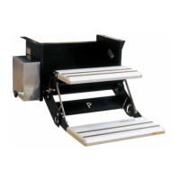
NOTE: For chassis with rear scissor jacks, go to Scissor
Jack Option. For chassis with telescoping rear jacks, go to
Telescoping Rear Jack Option.
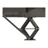
Scissor Jack Option
1. Starting with one of the rear scissor jacks, remove the
existing lower, outside pivot bolt. Replace pivot bolt with a
⁄” - 16 x 4” swing bolt.
A. Install swing bolt from rear-to-front with the shoulder of
the swing bolt to the rear side of the jack.
B. Place ⁄” washer and a ⁄” - 16 nylon locking nut onto
the threaded end of the swing bolt. Tighten nut enough so
that the swing bolt will only pivot by using a screwdriver
for leverage. Make sure the swing bolt tab is positioned
horizontally.
C. Prepare T-Bolts and stabilizer tubes as described in
step 12, except the inner tube should be set at 1” instead
of 5”.
D. After fully retracting rear scissor jacks, attach the clevis
end of the stabilizer inner tube to the swing bolt tab on the
rear side of the jack using a ⁄” - 16 x 1 ½” bolt with a ⁄”
Fig.9

 Loading...