M & MA Series Meters
10
Get the latest PDF manual:
https://www.lcmeter.com/resources/technical/manuals
Mobile/online version of this manual:
https://www.lcmeter.com/manuals
·
Meter Start Up and Operation
·
Reversing the Meter Registration
·
Setting the Standard Adjuster
How LC Meters Work
Liquid Controls meters are positive displacement meters. They are designed for liquid
measurement in both custody-transfer and process-control applications. They can be installed
in pump or gravity flow systems. Because of their simple design, they are easy to maintain,
and easy to adapt to a variety of systems.
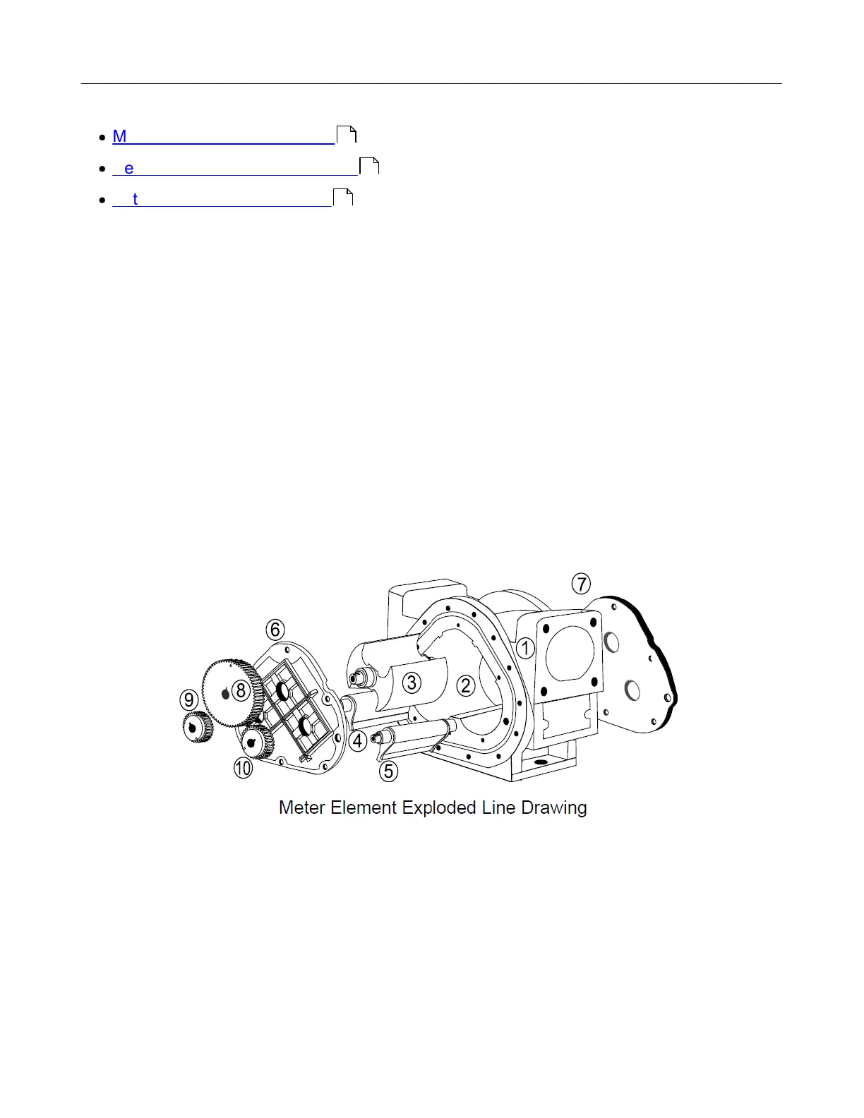
The meter housing (1) is designed with three cylindrical bores (2). Three rotors, the blocking
rotor (3) and two displacement rotors (4, 5), turn in synchronized relationship within the bores.
The three rotors are supported by bearing plates (6, 7). The ends of the rotors protrude
through the bearing plates. The blocking rotor gear (8) is placed on the end of the blocking
rotor. The displacement rotor gears (9, 10) are placed on the ends of the displacement rotors.
These gears create the synchronized timed relationship between the three rotors.
As fluid moves through the meter housing, the rotor assembly turns. The liquid is broken into
uniform sections by the turning rotors. Fluid displacement occurs simultaneously. As fluid
enters, another portion of the fluid is being partitioned and measured. At the same time, the
fluid ahead of it is displaced out of the meter and into the discharge line. Since the volume of
the bores is known, and the same amount of fluid passes through the meter during each
revolution of the blocking rotor, the exact volume of liquid that has passed through the meter
can be determined with a high degree of
accuracy.
16
18
20
 Loading...


