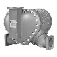
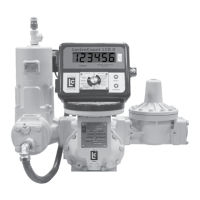
M & MA Series Meters
12
Get the latest PDF manual:
https://www.lcmeter.com/resources/technical/manuals
Mobile/online version of this manual:
https://www.lcmeter.com/manuals
Installation Requirements
WARNING
Under normal operation, do not expose any portion of the LP-Gas system to
pressures in excess of rated working pressures without an automatic safety valve
to vent the over pressure discharge to a place of safety away from the operator
and other people.
Failure to provide such a safety relief may result in leakage or rupture of
one or more of the components in the system. This can result in injury of
death from either the leakage or the debris from the rupture.
Class 10 LPG Meters - Codes
Class 10 LPG meters must be installed in accordance with the requirements of ANSI-NFPA
58 in addition to all other state and local codes.
Ensure that you do each of the following as part of the installation of your meter.
·
TAKE ALL NECESSARY SAFETY PRECAUTIONS – Make sure that all necessary safety
precautions have been taken. Provide for proper ventilation, temperature control, fire
prevention, evacuation and fire management.
·
PROVIDE ACCESS FOR FIRE EXTINGUISHERS – Provide easy access to the
appropriate fire extinguishers for your product. Consult with your local fire department and
state and local codes to make sure that you are adequately prepared.
·
READ PROVIDED LITERATURE – Read this manual as well as all the literature provided
in your red Owner Information Packet. If you have any questions, consult with your full-
service distributor or call the Service Department at Liquid Controls.
·
CONFORM TO ALL CODES – Install the meter and accessories in conformance with
applicable state and federal construction, electrical and safety codes.
·
LEAVE THREAD CAPS IN PLACE – Before shipment, protective thread caps are placed
in all meter and accessory openings. They should remain in place until you are ready to
attach piping.

 Loading...

