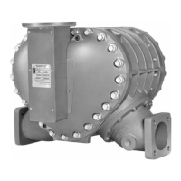
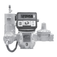
M & MA Series Meters
13
Get the latest PDF manual:
https://www.lcmeter.com/resources/technical/manuals
Mobile/online version of this manual:
https://www.lcmeter.com/manuals
·
FLUSH PIPING – Prior to meter installation, the entire piping system should be thoroughly
flushed of all debris with a liquid that is compatible with the construction of the meter.
·
KEEP EXTERNAL SURFACES OF THE METER CLEAN
·
MOUNT METER SECURELY – The meter must always be securely bolted to a platform
or supporting member, regardless of the mounting position of the meter. Never “hang” a
meter on the connecting piping.
·
PREVENT PIPE STRAIN OR STRESS – Prevent pipe strain or stress from occurring
when making meter or accessory repairs. Pipe strain and stress occurs when the pipes
are not supported or are not aligned correctly to the meter. The weight of the pipes must
always be supported independent of the meter. This means that the meter and
accessories can be easily removed without affecting the pipes or the pipe alignment.
Never leave any of the pipes hanging.
·
INSTALL METER ONLY ON THE DISCHARGE SIDE (DOWNSTREAM) OF THE
SYSTEM PUMP
·
APPLY PIPE COMPOUND TO MALE THREADS ONLY
·
LEAVE SPACE FOR FUTURE MAINTENANCE – Position the meter with service in mind.
Provide ample workspace. Removing covers can be difficult when work space is not
available. Always supply a platform or support for the meter mounting.
·
USE METER ONLY WITH SPECIFIED LIQUIDS – A meter is metallurgically designed to
be physically compatible with the type of liquid originally specified by the customer, and as
indicated on the Serial Number Plate. A meter should not be used with a liquid different
from the liquid originally specified, unless the physical characteristics and pH rating are
similar and the application has been checked with LC Sales and Engineering through your
full-service distributor.
·
INSTALL A STRAINER – Install a strainer on the meter inlet to avoid damage from foreign
matter, such as weld slag, from entering the system. The strainer must always be located
on the inlet side.
·
TAG FLOW DIRECTION – All meters are tagged identifying their direction of flow. Meters
are set with a flow direction of left-to-right as standard. However, when a meter is
ordered, the customer can specify that the flow be set from either direction. If the meter
register counts in reverse, the meter is reading the direction of flow in reverse. If this
occurs, the meter registration must be reset. For mechanical output meters, see
Reversing the Meter Registration on page 10. For electrical output meters, such as

 Loading...

