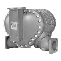
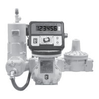
M & MA Series Meters
14
Get the latest PDF manual:
https://www.lcmeter.com/resources/technical/manuals
Mobile/online version of this manual:
https://www.lcmeter.com/manuals
meters equipped with a pulser or an electronic register, refer to the manual of the
electronic component.
·
USE CURRENT ENGINEERING DRAWINGS – Always request up-to-date, engineering
approved, dimensional drawings before starting any construction. Do not rely on catalog
pictures or drawings. They are for reference only. After receiving prints, check to see that
all equipment ordered is shown and that any extra pressure taps, plugs, etc. are noted
and their size specified.
Operation Requirements
Ensure that you are mindful of the following when operating your meter:
·
THE METER MUST REMAIN FULL OF PRODUCT AT ALL TIMES – An easy way to
accomplish this is to put the meter assembly in the line below the piping center-line (a
sumped position). This requires adding elbows and flanges prior to installing the meter.
The meter should be installed in a bypass loop, below the pipe center-line, with block
valves upstream and downstream of the meter inside the bypass loop. A block valve
should be located in the main pipeline and labeled as the bypass valve.
·
PIPING PRESSURE RELIEF – Any portion of pipe system that might isolate or block flow
should be provided with a pressure relief to prevent damage from thermal expansion.
There are excellent benefits to this type of installation. First, the meter is kept full. Second,
this type of installation allows the meter to be isolated for servicing and calibration while
continuing flow through the bypass valve.
·
MAINTAIN UPSTREAM LINES – Upstream lines must be maintained full to prevent air
from entering the meter. If upstream or inlet lines are constructed in a manner which
allows reverse flow, foot valves, or back checks must be installed.
·
UNDERGROUND TANKS, SUBMERSIBLE PUMPS – Underground tanks that are
furnished with a submersible pump will eliminate many problems that occur with positive
displacement pumps (suction pumps) when suction piping is incorrectly sized or when the
lift is too great.
·
API MANUAL OF PETROLEUM MEASUREMENT STANDARDS – Every meter should
be calibrated under actual service and installation conditions per the API Manual of
Petroleum Measurement Standards:
The following chapters of the API Manual of Petroleum Measurement supersedes the API
standard 1101:

 Loading...

