14 | Moku:Go Laser Lock Box User Manual © 2023 Liquid Instruments. All rights reserved.
Lower user interface
Use the lower user interface to either configure the locking stages or display the half screen
Oscilloscope or Data Logger.
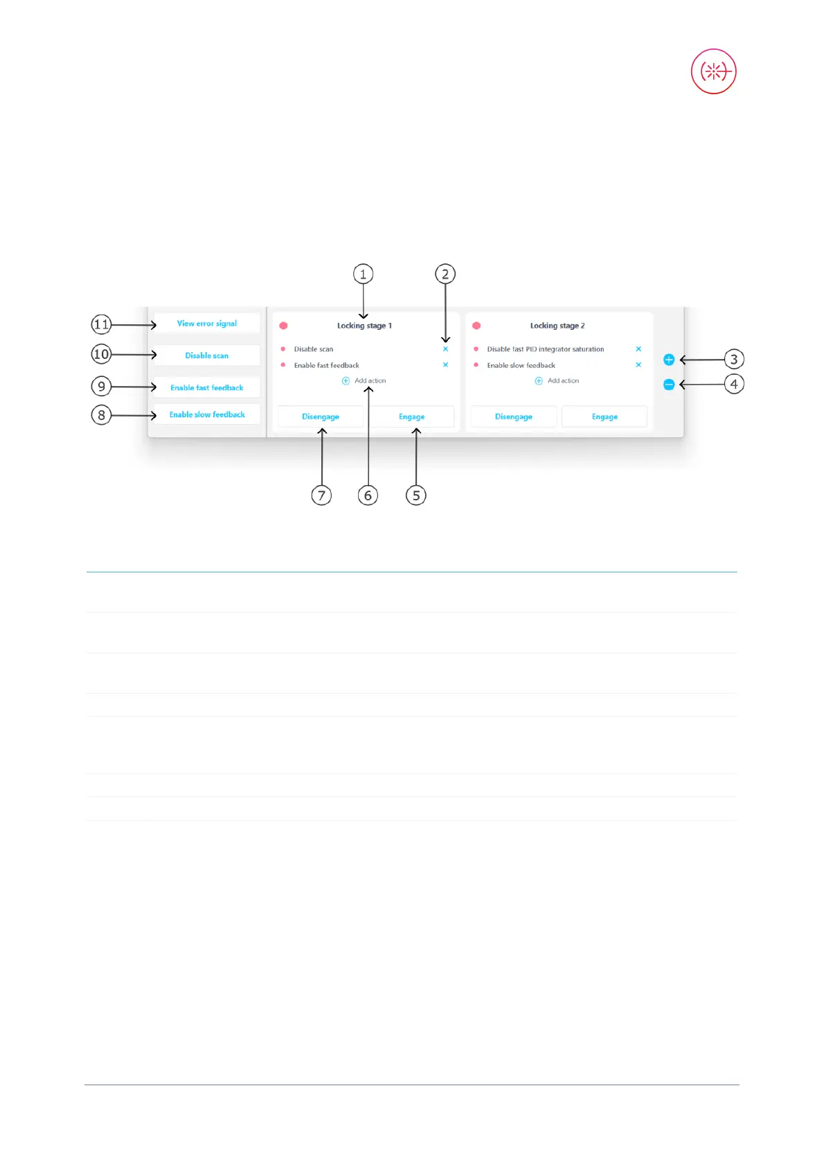
Locking stage
1 Lock stage 1 of (up to) 3 7
Disengage the actions defined in the
locking stage
2
Remove a certain action in the locking
stage
8
Tap to connect the slow PID to Output 1
to enable the slow feedback
3
Add a new locking stage (allows up to 3
stages at maximum)
9
Tap to connect the fast PID to Output 2
to enable the fast feedback
4
Remove a certain locking stage
10
Tap to enable/disable the scan signal
5 Engage the actions defined in the locking
stage
11 Tap to switch to the Oscilloscope to
view the error signal, where the user
can select the locking point
6
Add a new action in the locking stage
Add action
Choose any of the available actions to add to each locking stage. When engaged, all of the actions
associated with that stage will be enabled simultaneously.


 To Next Page