Page 6 Maxmig 210 IMA 578BLA
1. INSTALLATION
Machine Installation
1.1 Location
Place the welder where clean cooling air can freely
circulate in through the front louvers and out through the
rear louvers. Dirt, dust or any foreign material that can be
drawn into the welder should be kept at a minimum.
Failure to observe these precautions can result in
excessive operating temperatures and nuisance
thermostat trips.
1.2 Connection to Mains Supply
Before connecting the machine to the mains supply check
that the voltage and current capacity correspond to the
machine voltage and rated input current. Use a fuse or
C/B per AS3000 or local wiring rules.
The machine is supplied with an input lead and a 15A, 3
pin plug.
1.3 Shielding Gas Supply (For the Gas Metal
Arc Welding Process)
Refer “Safety in welding and cutting” - ANSI Standard Z49-
1 and WTIA Technical Note 7, available from the Welding
Technology Institute of Australia.
Obtain cylinder of appropriate type shielding gas for the
process being used.
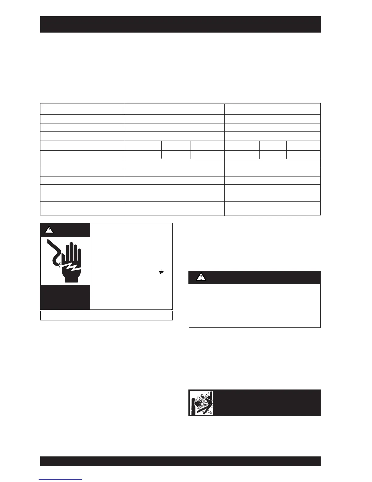
• Turn the input power off at
the disconnect switch
before installing or servicing
this machine.
• Do not touch electrically “hot”
parts such as output terminals
or internal wiring.
• Connect grounding screw ( )
to a good earth ground.
• Do not operate with covers
removed.
• Turn power switch “off” before
connecting or disconnecting
cables or other equipment.
PRODUCT DESCRIPTION
The Maxmig 250i is a fully integrated semi-automatic Constant Voltage DC arc welding machine. The Maxmig 210R offers a remote wire
feeder and a separate Constant Voltage DC arc welding machine. They combine a solid state power source with electronically controlled
wire feeding equipment.
Excellent arc characteristics are provided for both gas shielded and self shielded welding within its current range.
Standard features include a spot timer, gas purge facilities, a dual position 2 or 4 step trigger interlock, a Maxmig 150 MIG gun, a
regulator/flowmeter and gas hose, ground cable assembly (3m on the Maxmig 210i and 5m on the Maxmig 210R) a 3m long input lead
and an undercarriage on which a gas cylinder can be mounted.
WARNING
HIGH
VOLTAGE
can kill
Only qualified personnel should install or service this equipment.
CYLINDER may explode
if damaged
Model Maxmig 210i Maxmig 210R
Part No. 05-3210 (Integrated) 05-4210 (Remote)
Maximum Open Circuit Voltage 46V 46V
Output Current Range up to 210A up to 210A
Duty Cycle 25% 34% 100% 25% 34% 100%
Rated Output 210A/24.5V 180A/23V 120A/20V 210A/24.5V 180A/23V 120A/20V
Rated Input 240V single phase 50Hz 15 amps 240V single phase 50Hz 15 amps
Wire Speed Range 1-20 m/min 1-20 m/min
Weight (complete with u/c) 88 kg 107 kg
H x W x L (mm) Over lift
bail, cylinder tray & wheels 775 x 525 x 885 mm 1129 x 525 x 885mm
Operating Temperature -20˚C to 40˚C -20˚C to 40˚C
Specifications
Never connect the green/yellow conductor to any of the
active supply lines from the mains. This conductor is to
earth the machine as required by Electrical Regulations.
Once the above has been followed the machine can be
plugged into the mains outlet.
CAUTION