IMA 578BLA Maxmig 210 Page 9
f) Gas Purge *
Use the gas purge push button to operate the gas solenoid
to purge air from the hose after connecting a new gas
cylinder. Gas purge will only operate while the button is
held in.
g) Wire Inch *
Use this push button to operate the wire feed motor and
“cold” inch the wire.
h) 2T/4T Operation *
A two position switch on the front panel provides two
modes of operation of the gun trigger. In 2T mode, the gun
trigger is pressed to start welding and released to stop.
In 4T mode, pressing the gun trigger only operates the gas
solenoid, allowing shielding gas to flow. Releasing the
trigger activates the contactor which starts the wire feed
motor and connects welding current to the wire so that
welding may commence. To stop welding, the trigger must
again be operated; pressing it stops the wire feed,
activates the burn back time delay and opens the
contactor after the pre-set burn back time. Releasing the
trigger stops the gas flow.
To recommence welding, the above cycle must be
repeated.
i) Over temperature light
Indicates that the thermostats have operated to protect
unit from over temperature.
* Mounted on machine control panel for Integrated units.
Mounted on remote wire feeder for Remote units.
3.Setting Up for Welding
The following items are required:
1) A reel of wire of suitable size and type .
2) A suitable gun and cable assembly with a “Euro”
connector and the correct tip and, if necessary gas
nozzle for the consumable being used. (A Maxmig 150
MIG gun is supplied).
3) Correct drive rolls for the wire size and type to be used.
The wire feeder is supplied with a 0.9/1.2mm hard wire
feed roll as standard; drive rolls for other types and
sizes are available as spare parts. (see table on page
10).
4) A work return cable and clamp.(supplied)
5) Normal welding accessories including helmet or hand
shield with suitable lens, gloves etc.
6) If a gas shielded process is to be used, a cylinder of
appropriate gas is required. (Regulator/flowmeter and
hose are supplied.) If gas shielding is required, connect
the gas hose.
Remember that gas cylinders may explode if damaged, so
ensure that all gas cylinders are securely mounted.
Ensure that the correct type and size wire feed rolls are fitted. In
replacing wire feed rolls, ensure that the key and keyway are
correctly positioned and tighten the knurled locking screw
securely.
Fit a spool of appropriate wire onto the 50mm spool hub so that,
for the integrated model, as wire is fed the spool turns anti-
clockwise when looking at the spool. For the remote unit, the unit
spool must turn clockwise as the wire is fed. Carefully release
the end of the wire from the spool ensuring that the released end
is held to stop the wire from unravelling. Cut off the end kink to
give a smooth straight end of wire.
Obtain a gap between the wire feed roll and the pressure roll by
lifting the cam latch. Feed the wire end into the guide tube,
between the drive rolls, and into the “Euro” connector guide until
it protrudes about 20mm out of the front of the “Euro” connector.
Close the drive rolls by lowering the cam latch ensuring the rolls
firmly hold the wire. Adjust the tension so that wire feeds
smoothly.
Do not overtighten.
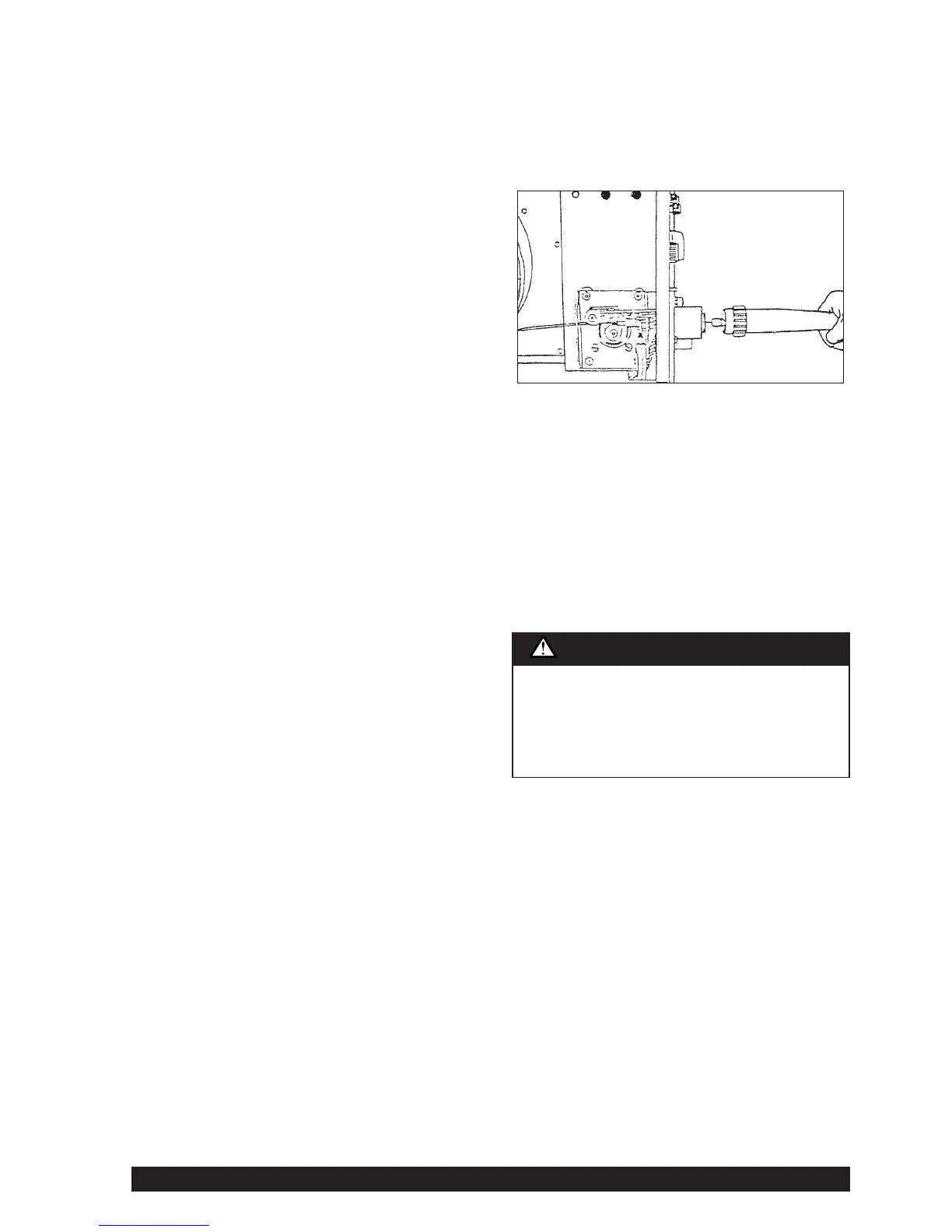
Fit the gun and cable assembly onto the “Euro” connector by
slipping the end of wire into the cable wire hole. Tighten the
“Euro” connector lock ring.
Activate the power source, set the wire feed speed to 4 on the
dial and press the wire inch push button. The wire feed roll
should turn, feeding the wire further up the gun and cable
assembly.
Ensure there are no kinks or sharp bends in the gun cable and
hold the wire inch button until the wire emerges from the gun. It
is good practice to remove the tip when first feeding a new coil of
wire, then refitting over the wire and tightening.
Cut off the end of the wire leaving 10mm to 15mm stick-out.
Select required polarity. See Section 1.5 - Output Polarity
Connection.
4.Welding
Put into 2T mode.
Select the output voltage required to suit the job by setting the
coarse and fine rotary switches.
Before beginning welding, ensure the wire protrudes from the
gun tip by approximately 10-15mm. Ensure welding shield and
other protective clothing are in place. Present the protruding
electrode just off the work. Maintain a steady grip on the gun,
protect your eyes with a welding shield, then press and hold the
gun trigger to create the arc.
If it is necessary to adjust the weld voltage, stop welding before
changing either or both of the rotary switches.
Adjust the wire feed speed as necessary to suit the job. At the
completion of the weld, release the gun trigger and pull the gun
away from the work to stop the arc.
4T mode should only be used for long welds by experienced
operators.
Integrated machine
When the gun trigger is pressed (2T mode) or pressed
and released the first time (4T mode), the wire is at
welding voltage. The wire should never touch the case of
the wire feeder. If it does, it is possible for the wire to arc
to the case.
Any wire overrun should be avoided.
WARNING