Page 8 Maxmig 210 IMA 578BLA
2. OPERATING INSTRUCTIONS
2.1 Duty Cycle
The machine is rated at the following duty cycles:
(1) Based on 10 min. time period (i.e., for 25% duty cycle, it is
2.5 minutes actual welding and 7.5 minutes with no welding
output, but with the input power remaining on keeping the
cooling fan operative.)
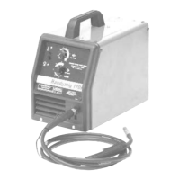
2.2 Control Panel
a) Power Switch
The mains power switch is incorporated in the “coarse”
output voltage control rotary switch. In the “0” positions the
input mains power is switched off.
b) Pilot Light
This light illuminates when the input mains power is
switched on.
c) Volts Control
The output voltage is controlled by two rotary switches.
One rotary switch provides two “coarse” voltage settings
as well as switching the mains power on. The other rotary
switch provides the user with a selection of eight “fine”
voltage settings. The selection between these two
switches allows the user to select any one of sixteen
welding voltages.
The approximate weld voltages for the switch positions
are:
d) Wire Feed Speed Control *
Use this control to adjust the speed at which the electrode
wire feeds when welding. This is in effect a current control
as the power source will deliver the current necessary to
melt the wire. The higher the speed, the more current will
be required. Wire feed speed range is approximately 1 to
20 meters/min (40 to 790 inches/min.).
Operation of the gun trigger switches the wire feed motor
on and off, depending upon the mode setting. The wire
feed motor is dynamically braked to minimise wire overrun
after welding has ceased.
Welding voltage is available immediately the gun trigger is
operated, but when welding is stopped there is a factory
set delay of approximately 1/2 sec. after wire feed has
stopped to allow the electrode to burn back slightly and
prevent sticking in the crater.
e) Spot Welding *
In spot welding mode welding takes place for a pre-set
time and then stops automatically. Welding time is
adjustable between 0.5 sec. and 4 sec. by operation of the
spot weld control on the front panel. There is a positive
click in the extreme anti-clockwise position to indicate that
the spot weld feature is “off”.
* Mounted on machine control panel for Integrated units.
Mounted on remote wire feeder for Remote units.
Duty Cycle
(1)
Amps Volts
25% 210 24.5
34% 180 23
100% 120 20
Coarse Fine Volts Coarse Fine Volts
1 1 13.0 2 1 18.0
1 2 13.5 2 2 19.0
1 3 14.0 2 3 20.0
1 4 14.5 2 4 21.0
1 5 15.5 2 5 22.0
1 6 16.0 2 6 23.0
1 7 17.0 2 7 24.0
1 8 17.5 2 8 25.5
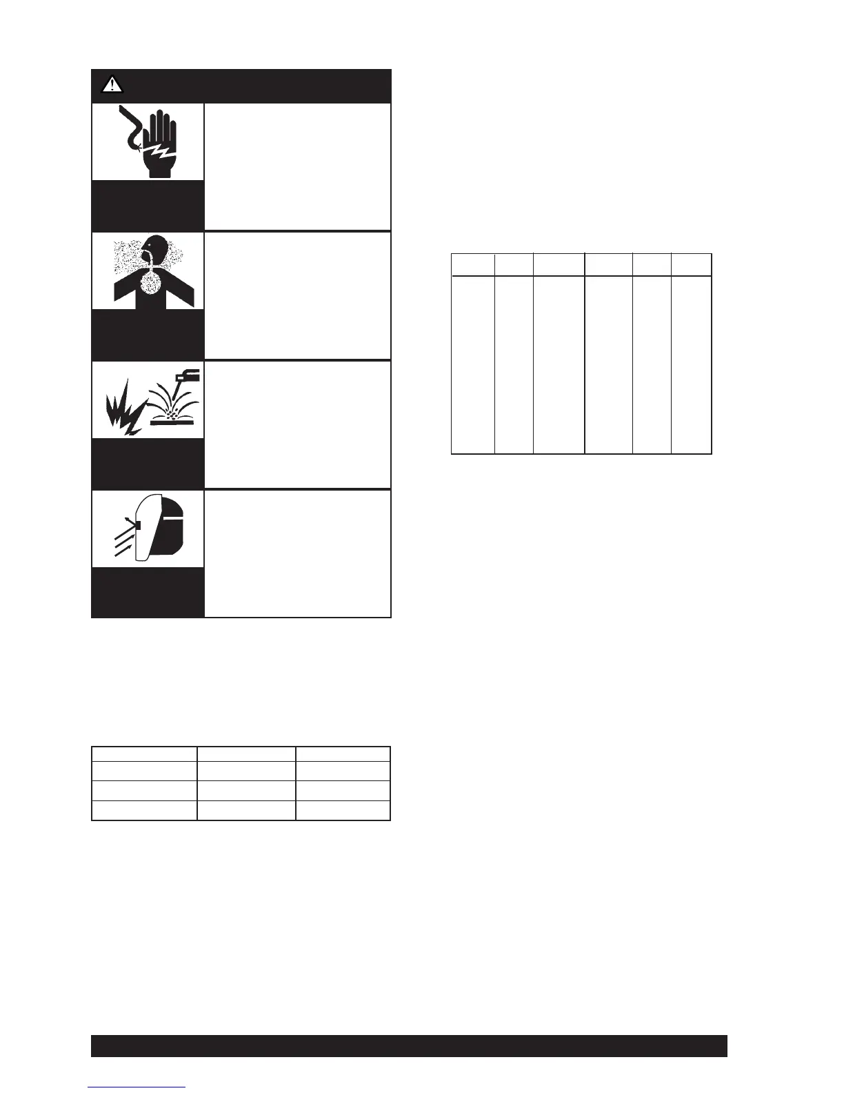
WARNING
ELECTRIC
SHOCK
can kill
FUMES AND
GASES can be
dangerous
WELDING SPARKS
can cause fire
or explosion
ARC RAYS
can burn.
• Do not touch electrically live
parts or electrode with skin or
wet clothing.
• Insulate yourself from work
and ground.
• Always wear dry insulating
gloves.
• Keep your head out of fumes.
• Use ventilation or exhaust to
remove fumes from breathing
zone.
• Keep flammable material
away.
• Do not weld upon containers
which have held
combustibles.
• Wear eye, ear and body
protection.
IMPORTANT SAFETY NOTE: In 2T mode {refer 2.2 (h)}, this
DC Constant Voltage wire welder provides “COLD” electrode
when the gun trigger is not operated. Conversely, the output
terminals are “LIVE” when the gun trigger is “activated” when
pressed in 2T mode, or triggered on in 4T mode.