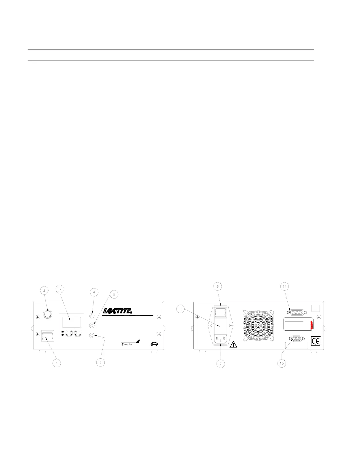
2. Description (continued)
3. Control Timer
The Control Timer may be programmed for any exposure length up to 999.9s. Once the
desired exposure time is entered, hit Reset to save the value.
4. Power Indicator Light
When illuminated green, indicates that the power supply is functioning and the fans are on.
5. Cure Light On Indicator Light
When the CureJet
TM
curing light is on and functioning correctly, this light will illuminate
blue.
6. Fault Indicator Light
If the CureJet
TM
LED System is in a Fault condition this light will illuminate red.
7. Power Inlet Module
Connect AC Line Cord to power inlet module.
8. On/Off Switch
The On/Off Switch turns the controller power and the cooling fans on.
9. Fuse Holder
(2) 5x20mm 4 amp fuses are contained within.
10. External Switch Connection XS 1
The Loctite
®
CureJet
TM
LED System can also be actuated by an external foot switch,
Loctite®
P/N 97201.
11. To CureJet
TM
Connection
The Loctite
®
CureJet
TM
Controller must be connected to a CureJet
TM
LED to operate
correctly. Use only Loctite
®
Cables P/N 1370351 or 1370352 for interconnect.
RESET
LOCK
UP
DOWN
o -
12
345
A2 A1
TIMER
Panasonic
LT4H
POWER
CURE LIGHT ON
FAULT
START
MANUAL MODE
TIMED MODE
XS 1
TO CUREJET™
Warning
Manual Before Servicing Unit.
Disconnect and Refer to
INPUT:
85-264 VAC
50 / 60 Hz
MAX 2.7 A
FUSE:
3 AMP
240 VAC
MADE IN U.S.A
FOR SPARE PARTS, MANUALS, REPAIRS,
OR TECHNICAL ASSISTANCE:
Visit us at equipment.loctite.com
or call Henkel Corp. at:
USA - (1) 860-571-5174
Germany - (49) 89-9268-0
Singapore - (65) 6482-3881
Label P/N: 988341
RoHS
Compliant
Label P/N 8900605
Patent Pending
LEDs
TM
For:
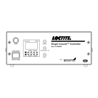
Single CureJet™ Controller
Item # 1364033
Figure 1