4. Operating the Unit
21
543
A1 A2
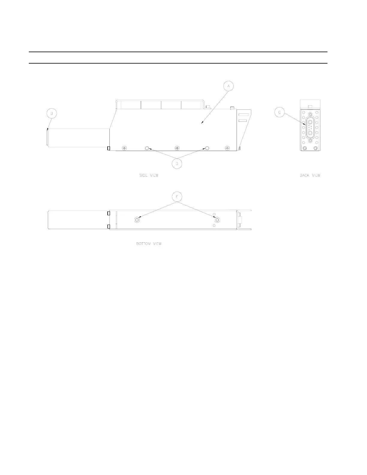
Figure 2
4.1 Installation, refers to Figures 1 and 2
1. Place the LED Controller on a flat sturdy surface.
2. If the CureJet
TM
will be operated from a fixed position, it may be mounted in the following
manners:
A. Holes (D) on the sides of the CureJet
TM
are properly sized for M4 screws. If you
wish to mount the CureJet
TM
to the side of the LED Controller, kit is included.
B. Tapped inserts (E) on the bottom of the CureJet
TM
are for M4 screws. Do not thread
screws deeper than .25 inches (6.35mm).
3. Using either Loctite
®
Cables P/N 1370351 or 1370352, connect the CureJet
TM
to the LED
Controller (Figure 2 Item C to Figure 1 Item 11).
4. If it will be used, plug in Foot Switch to LED Controller (Figure 1 Item 10).
5. Plug in AC Line Cord to LED Controller (Figure 1 Item 7).
4.2 Operation
1. Turn on the On/Off Switch on the back of the LED Controller unit (Figure 1 “8”).
2. Fans on both the CureJet
TM
and LED Controller unit should be on. The Power indicator
light should be on.
3. If Timed Mode is desired, set Mode Switch (Figure 1 “1”) to Timed Mode and program the
control timer (Figure 1 “3”) to the desired exposure time.
4. Depress Start Button (Figure 1 “2”) or Foot Switch to activate light.