EasyManua.ls Logo

Loctite 97152 User Manual

Loctite 97152
48 pages
To Next Page IconTo Next Page
Page #1 background imageLoading...
Page #1 background image
Operating Manual
Bedienungsanleitung
Universal-Steuergerät
Dual Channel Controller
97152

Table of Contents

Question and Answer IconNeed help?

Do you have a question about the Loctite 97152 and is the answer not in the manual?

Loctite 97152 Specifications

General IconGeneral
BrandLoctite
Model97152
CategoryController
LanguageEnglish

Summary

Safety and General Information

Emphasized Sections

Explains DANGER, CAUTION, and NOTE signal words.

Items Supplied

Lists the components included with the controller.

Safety Instructions

Provides essential safety guidelines for operation.

Field of Application (Intended Use)

Describes the controller's intended purpose and capabilities.

Product Description: Theory of Operation

Controller Architecture and Function

Explains the internal workings and components of the controller.

Product Description: Controls and Connections

Front Panel Display and Selector Button

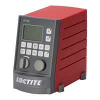
Details the main display and the selector/confirm button.

Product Description: Control Panel Keys

Keys for Channel Selection and Adjustment

Describes keys for channel selection and parameter adjustments.

Product Description: Control Panel Keys

Keys for Program Selection and System Control

Details keys for program selection and system functions like ESC/Lock.

Product Description: Control Panel Keys

Keys for Setup, Priming, and Reservoir Control

Explains keys for setup, priming feed lines, and reservoir control.

Product Description: Pneumatic Interfaces

Reservoir and Valve Connection Ports

Details pneumatic connection ports for reservoir and dispense valves.

Product Description: Electrical and Communication Interfaces

I/O, Serial, Flow Monitor, and PLC Ports

Describes connection ports for I/O, serial, flow monitors, and PLC.

Product Description: Peripheral Module Connections

External Valve, Rotor, and Drive Connections

Details connections for external valve modules, rotors, and DC drives.

Product Description: Display and Status Information

Start Display Overview and Program Step Codes

Explains the initial display and status numbers for program steps.

Product Description: Operational Modes and Security

Controller Access Function and PIN

Details the security feature for controller access.

Time Controlled Mode Operation

Describes operation using internal timing for dispensing.

Continuous Mode Operation

Describes operation synchronized with external controllers.

Product Description: Menu System and Peripherals

Menu Types Overview

Categorizes menus into On/Off, Selection, and Value setup types.

Peripheral Connection Options

General information on connecting various peripherals.

Product Description: Integrated Valve Modules

1 Dispense Channel Configuration

Lists components for a single dispense channel system.

2 Dispense Channels Configuration

Lists components for a two-channel system without advancing slide.

Product Description: External Valve Module

2 Dispense Channels Configuration

Details components for a two-channel system using an external module.

Product Description: Factory Settings

Default Configuration Parameters

Lists the default factory settings for dispense channels and system setup.

Technical Data

Electrical Specifications

Details power supply, consumption, fuse, and protection ratings.

Pneumatic Specifications

Covers pneumatic supply quality, pressure, and hose sizes.

Dimensions and Environmental Data

Provides physical dimensions, operating, and storage temperatures.

Installation

Environmental and Space Requirements

Specifies operating conditions and required installation space.

Connecting, Starting, and Shutting Down the Unit

Step-by-step guide for unit connection, startup, and shutdown.

Operation: Programming Basics

Controller Security and System Setup

Covers controller locking/unlocking and initial system setup.

Programming Workflow and Procedure

Outlines the general steps for programming dispensing applications.

Operation: Dispense Channel Configuration

Configuring Channels, Setup Mode, and Timing

Details channel setup, entering setup mode, and timing adjustments.

Further Adjustments and Setup Verification

Covers additional adjustments and checking the setup.

Operation: System Setup Menu

Language Selection

Option to select the user interface language.

Valve and Channel Configuration

Selection of dispense channels and valve modules.

Resetting to Factory Defaults

Procedure to reset all settings to factory defaults.

Operation: Program Selection and I/O Status

Program Changeover Types and I/O Signal Status

Details program selection methods and I/O signal status.

Operation: Dispense Channel Setup Menu

Configuring Peripherals for Channels A and B

Defines activation options for peripherals per dispense channel.

Operation: Setup Mode Functions

Manual Operation and Unit Actuation

Allows manual switching of channels and unit actuation.

Operation: Timing and Motor Speed Settings

Setting Dispense, Pre/Post-Delay Times, and DC Motor Speed

Adjusts dispense times, delay times, and DC motor speed.

Operation: Online Flow Monitor

Flow Monitor Value and Limit Setup

Sets tolerance, evaluation start/stop points, and measuring time factor.

Reference Dispensing Activation

Enables or disables reference measurement for flow monitoring.

Operation: Reservoir and Program Management

Reservoir Pressure, Signals, and Program Selection

Manages reservoir pressure, signals, and preselects dispense programs.

Operation: Dispense Time Adjustment

Adjusting Dispense Time for Product Amount

Explains how to adjust dispense time for required product amount.

Operation: Dispense Time Factors

Product Viscosity, Needles, and Pressure Considerations

Details product viscosity, needle types, and pressure for timing.

Operation: Online Flow Monitor Functionality

Flow Monitoring Principles and Malfunctions Detected

Explains how flow monitoring detects application issues.

Operation: Activating Flow Monitoring

Display Screens in Time and Continuous Modes

Shows display differences for time and continuous flow monitoring modes.

Operation: Flow Monitor Parameter Tuning

Setting Tolerance and Evaluation Limits

Configures tolerance values and evaluation start/stop points.

Operation: Flow Monitor Measurement Settings

Measuring Time Factor and Reference Cycle Setup

Sets measuring time factor and performs reference dispensing cycles.

Operation: Flow Monitor Status Interpretation

Understanding Flow Monitor Status Screens

Explains the meaning of status indicators on the flow monitor screen.

Troubleshooting

Guide to Common Malfunctions and Solutions

Lists common problems and their corrective actions.

Annex: Spare Parts and Wiring

Spare Parts and Accessories List

Lists available spare parts and accessories.

XS 1 Start Connector and Foot Switch Wiring

Details pin assignments for XS 1 and foot switch wiring.

Annex: XS 2 Product Reservoir Wiring

Digital and Analog Level Sensor Connections

Wiring diagrams for digital and analog level sensors for XS 2.

Annex: XS 3 and XS 5 Interface Wiring

Flow Monitor and RS232 Serial Interface Connections

Wiring details for XS 3 Flow Monitor and XS 5 Serial Interface.

Annex: XS 8 and XS 10 PLC Wiring

I/O Port and PLC Internal Power Supply Connections

Wiring for XS 8 I/O Port and XS 10 PLC internal power supply.

Annex: XS 10 PLC and XS 11 DC Drive Wiring

PLC External Power Supply and DC Drive Connections

Wiring for XS 10 PLC external power and XS 11 DC Drive.

Annex: Peripheral Module Wiring

External Valve, Rotor, and Proximity Switch Connections

Wiring for XS 12, XS 16, XS 17/18 modules.

Annex: Regulatory Information

EC Declaration of Conformity

Manufacturer's declaration of conformity to EC regulations.

Related product manuals