89
7 Annex
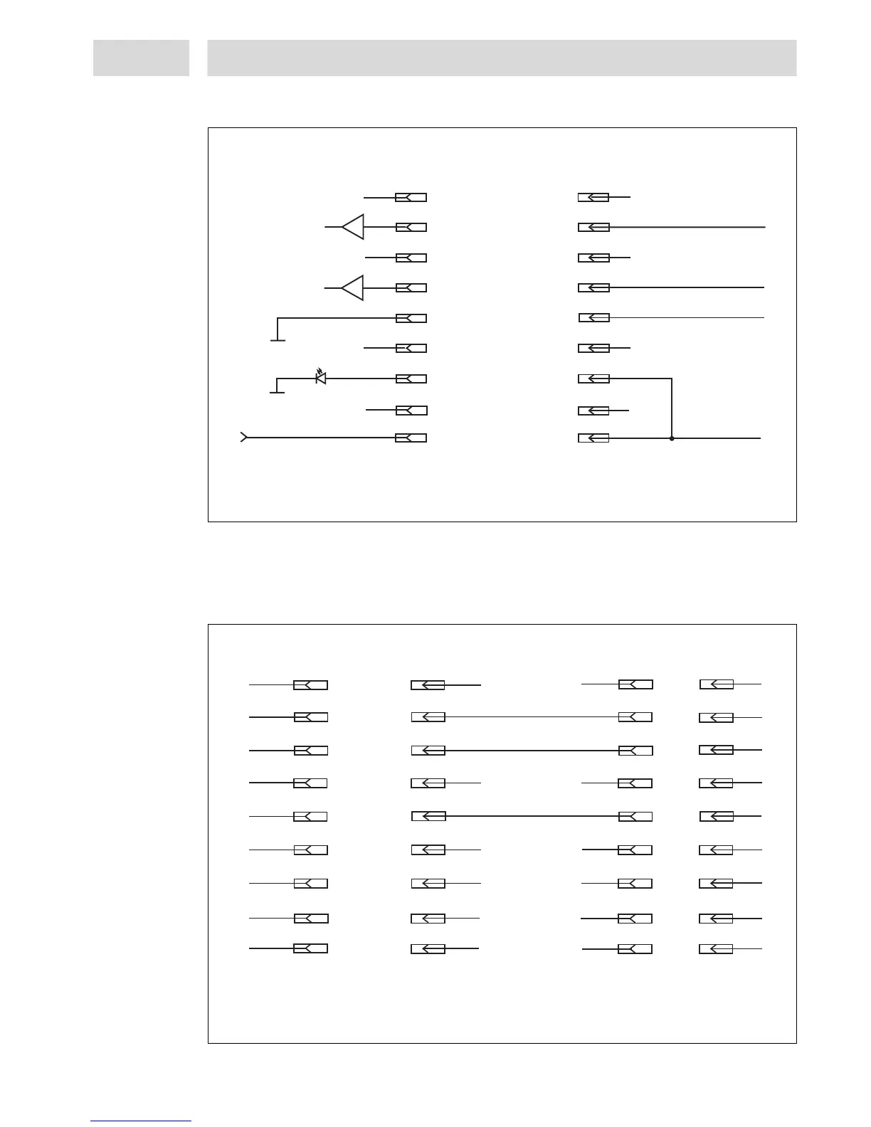
7.2.3 XS 3 Flow monitor
7.2.4 XS 5 Serial interface RS232
To be connected via serial cable, pins 7 and 8 must not be assigned. Observe the serial interface
protocol.
9600 baud/1stop bit/no parity/8 data bits.
1
2
3
4
5
6
7
8
9
1
2
3
4
5
6
7
8
9
Sensor Signal B
0-10VDC
Identification
Signal
Analogue/IN
Controller
+ 24VDC
Sensor Signal A
0-10VDC
Analogue/IN
GND
All other pins may never be connected!
Pre-Amplifier
1
2
3
1
2
3
4
5
6
7
8
9
4
5
6
7
8
9
Controller
PC
1
2
3
4
5
6
7
8
9
1
2
3
4
5
6
7
8
9
Connection Cord
Rx
Tx
Gnd
*
Rx
*
Tx
All other pins may never be connected!
* The pins can be used ONLY for firmware updates!