82
5 Operation
5.11.1 Actuate flow monitoring
• Push the key for the channel for which the monitoring function is to be activated.
Screens displayed are different for each operating mode.
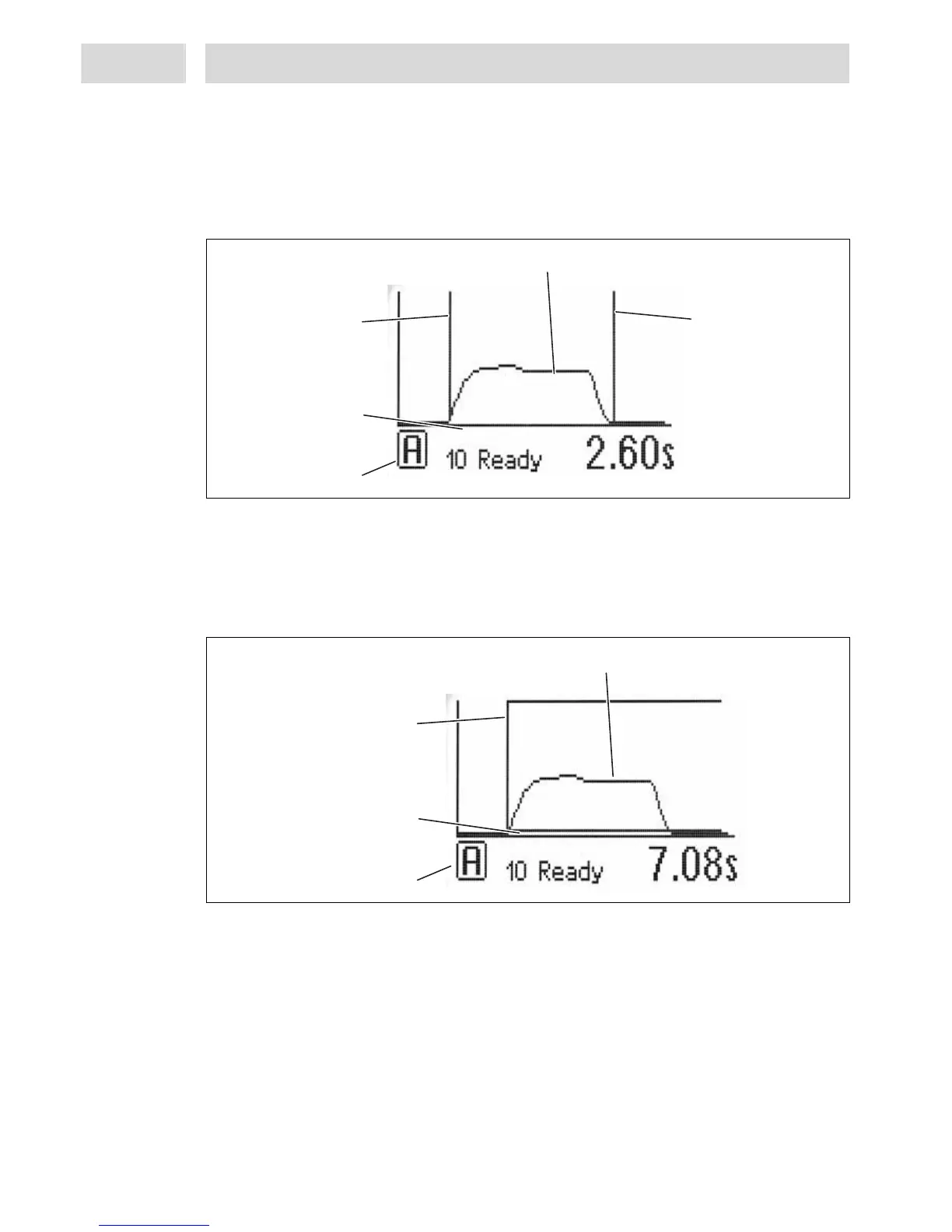
Screen display in time-controlled mode
– Status line – see section 2.6.2.
– X-axis dispense, length 120 pts (0- 119 pts) – the two boundary lines can be shifted within this
range, see section 5.8.2.
– Boundary lines for start and end of measurement
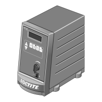
Screen display in continuous mode
– Displayed range within which a measurement is OK. Range is determined by the controller and
displayed graphically, taking into account the preselected tolerance as well as the measured
reference.
Status line
X-Axis Dispense,
Lenght 120 pts.
Measurement curve
Boundary line
Measurement
Start of Evaluation
Status line
X-Axis Dispense,
Lenght 120 pts.
Measurement curve
Boundary line
Measurement
Start of Evaluation
Boundary line
Measurement
End of Evaluation