1 - 13
CRT: 4:3 16:9
Test pattern: Test pattern:
- 50Hz 4:3 16:9
- 60Hz 4:3 16:9
Adjustment procedures
Service Mode A 2400 30.05.2000
High voltage at zero beam: 0 Max high voltage: ß
Picture size UB (NTSC Mode) High voltage
33" / 4:3 142 V
32" / 16:9 136 V
146 V
0 31,0 kV
ß 32,0 kV
0 33,0 kV
ß 34,0 kV
0 33,0 kV
ß 34,0 kV
32" / 16:9
Real flat
High voltage at zero beam:
0 Max high voltage: ß
Picture size UB (1080i Mode) High voltage
Measuring UB parallel to C651
Measuring UB plus pole C651 to Chasssis GND
33" / 4:3 150 V
32" / 16:9 156 V
160 V
0 31,0 kV
ß 32,0 kV
0 33,0 kV
ß 34,0 kV
0 33,0 kV
ß 34,0 kV
32" / 16:9
Real flat
Table–1
OK
M
Service
Service
Geometry
Cutoff
White drive
Option bytes
More . . .
More . . .
Colour VCO: main
Colour VCO: PIP
Adjustments
System data
System data
OK
M
E
back
end
OK
M
E
back
end
Chassis A24
Software version V1.3
EPROM code 24. 11. 2000
EAROM code @00700
Operating time 110h
M
E
back
end
1. Function
Service mode permits the calibration of variable EAROM values.
2. Entering Service Mode
The Adjustment sequence for the service mode is indicated in the pictures:
“Arrangement of the service mode commands on the remote control” (p. 11).
The set is now in the service mode basic routine and documents this with the
following on-screen display.
3. Instructions on Geometry Alignment
Vertical amplitude, Vertical position, Vertical linearity, Vertical symmetrie, Hor.
amplitude, Hor. phase, E-W corr., Trapezium comp., etc will be adjustet
separately for 50/60Hz vertical frequencies. Therefore they have to be regulated
separately.
B
HV-GND
KR
G2
KG
G1
f
f
KB
MP1
MP2
MP3
I3390
U
G2
I3380
I3371
W3152
W3154
W3258
W3362
W3201
R
FB
G
B
GND
GND
GND
GND
U
SVM
GND
U12
CUTOFF
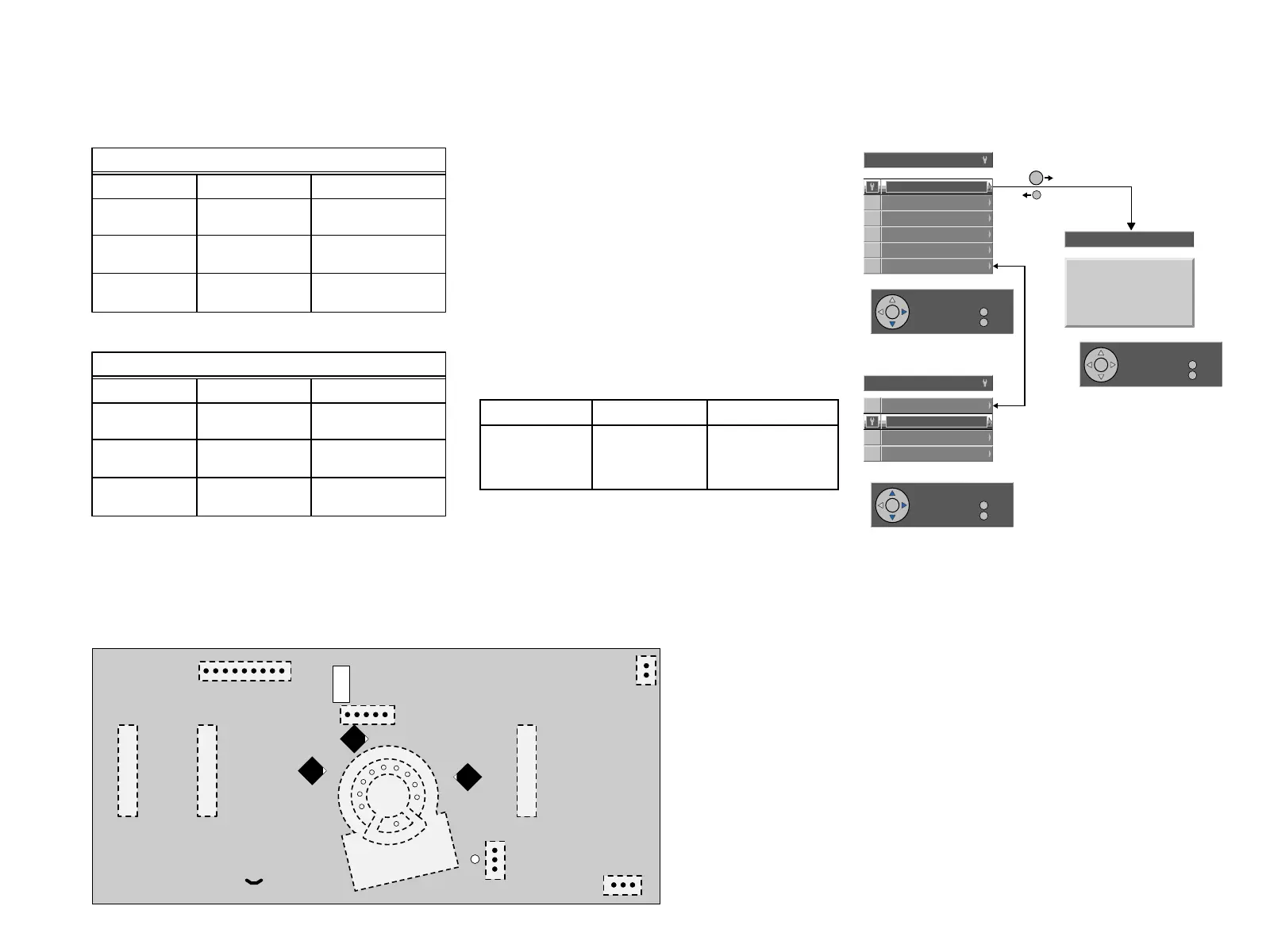
Picture tube board & SVM
Solder side
Uvid
U
f
Service Layout diagram
11
12
9
8
10
V 001
7
6
5
4
1
G
R
 Loading...