1 - 4
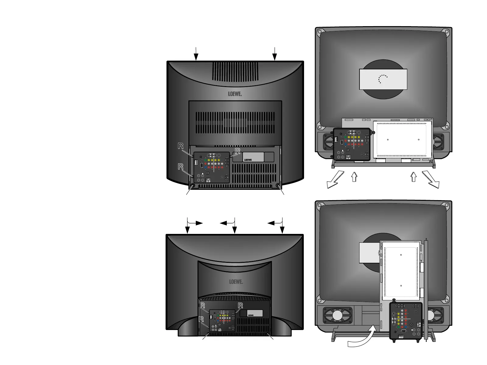
Rear panel removal
Unscrew the five rear panel screws R to remove the rear panel.
Insert screw driver into recess V. Depress interlocking and at the
same time slide rear panel to the rear (fig. 2a).
ACO 9303 MB / Press interlocking in direction of arrows and at
the same time slide rear panel to the rear (fig. 2b).
How to move the chassis into the service position
1. Hold and lift the rear of the chassis and gently pull the chas-
sis toward you (fig. 3).
2. Undo the cable fixtures. Turn the chassis through 90°anti-
clockwise and place the chassis behind the set (fig. 4).
3. After servicing ensure all wiring is returned to its original po-
sition and fixed.
Service position for the signal board
1. Remove the signal board from the main chassis (Basic board),
ensuring all leads are disconnected.
2. Remove the four six (A) (fig. 5) from the plastic AV cover and
unclip the AV cover from the signal board.
3. Remove the front metal cover from the signal board (fig. 6).
Do the same for the rear metal cover (fig. 7).
4. Fit the three extension leads to the signal board making sure
that the signal board does not touch the basic board (fig. 8).
5. After servicing ensure all wiring is returned to its original po-
sition and fixed.
Note:
The extension lead wire kit is supplied as a service kit. (Part
number 3 x 396-90288.938).
☞ Repair information for the signal board
MediaPlus
There is any error on the signal board, please proceed as de-
scribed:
- Remove the EAROM (I 1891) from the printed circuit board. The
TV is able to keep running.
- If you get a static picture, the EAROM is out of order (possible
geometry errors remain unconsidered).
- If the error is still there, it's because of another component on
the signal board.
- If you want to change the signal board at the service head office,
insert the EAROM from the damaged signal board into the new
one. So you don't need to make the alignment and the program-
ming of the TV set.
Important!
Please remove the AV cover at the damaged signal board.
Rear panel removal
How to move the chassis into the service
position
Fig. 3
ANTENNA
LOOP B
1
INPUT
SERVICE
SUBWOOFER
STAND
CLASS 2 WIRING
TUNER MONITOR AUDIO
OUTPUT
2
Y
Cb
C
r
V
L
L
R
R
AUDIO
VGA
RRRR
LLLL
VVV
S-VIDEO S-VIDEO R
C-VIDEO
VGA
EXT. SP.2
CLASS 2 WIRING
IR
RC5/
RC6
Fig. 4
90°
ANTENNA
LOOP B
1
INPUT
SERVICE
SUBWOOFER
STAND
CLASS 2 WIRING
TUNER MONITOR AUDIO
OUTPUT
2
Y
Cb
C
r
V
L
L
R
R
AUDIO
VGA
RRRR
LLLL
VVV
S-VIDEO S-VIDEO R
C-VIDEO
VGA
EXT. SP.2
CLASS 2 WIRING
IR
RC5/
RC6
VV
Fig. 2a
R
R
R
RR
ANTENNA
LOOP B
1
INPUT
SERVICE
SUBWOOFER
STAND
CLASS 2 WIRING
TUNER MONITOR AUDIO
OUTPUT
2
Y
Cb
C
r
V
L
L
R
R
AUDIO
VGA
RRRR
LLLL
VVV
S-VIDEO S-VIDEO R
C-VIDEO
VGA
EXT. SP.2
CLASS 2 WIRING
IR
RC5/
RC6
Fig. 2b
R
R
R
R
VVV
ACO9303
R
ANTENNA
LOOP B
1
INPUT
SERVICE
SUBWOOFER
STAND
CLASS 2 WIRING
TUNER MONITOR AUDIO
OUTPUT
2
Y
Cb
C
r
V
L
L
R
R
AUDIO
VGA
RRRR
LLLL
VVV
S-VIDEO S-VIDEO R
C-VIDEO
VGA
EXT. SP.2
CLASS 2 WIRING
IR
RC5/
RC6