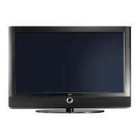
Do you have a question about the Loewe Spheros R 32 HD+ 100 and is the answer not in the manual?
Guidelines for handling components at MOS workstations with electrostatic shielding.
Regulations for repair, modification, and testing of electronic devices.
Recommendations for handling sensitive components at MOS workstations.
Regulations for repair, modification, and inspection of electronic devices.
Procedures for handling MOS components safely.
Regulations for repair, modification, and testing of electronic devices.
Instructions on how to access the TV's service mode using the remote.
Selecting specific alignment functions within the service menu.
Settings for saving services, core supply, standby mode, and CI messages.
Settings for LCN sorting, 16:9 voltage, and factory modes.
Options for HDMI mute, program switching, and EPG.
Options for tuner allocation, DVB-T recognition, and decoder errors.
Options for front socket, AV switching, and demo modes.
Settings for software flashing, clock display, and local operation.
Options for contrast adjustment and hotel TV mode.
Settings for chroma output, receiver modes, and VGA input.
Factory mode and tuner AGC bandwidth settings.
Settings for tuner bandwidth, scrambled programs, and DVB tuners.
Options for terrestrial tuners and cable tuners.
Settings for videotext descriptor, HDR, and DVB-T antenna.
Displays TV application and firmware versions, chassis, and operating time.
Access to various option bytes for configuration.
Information about system hardware and software.
Accessing and configuring various option bytes.
Procedures for updating TV and DVB software.
Schematic diagram of the Basic Board.
Component placement diagram for the Basic Board.
Solder side layout of the Basic Board.
Schematic diagram of the FRC board.
Second part of the FRC board schematic.
Component placement diagram for the FRC board.
Solder side layout of the FRC board.
Schematic diagram for the MPEG Encoder module.
Component placement diagram for the MPEG Encoder.
Solder side layout for the MPEG Encoder.
Schematic diagram for the AC3 module.
Component placement diagram for the AC3 module.
Solder side layout for the AC3 module.
Schematic diagram for the Connector Board.
Component placement diagram for the Connector Board.
Solder side layout for the Connector Board.
| Screen Size | 32 inches |
|---|---|
| Resolution | 1366 x 768 pixels |
| HD Type | HD Ready |
| HD Support | 720p |
| Display Technology | LCD |
| Aspect Ratio | 16:9 |
| HDMI Ports | 2 |
| USB Ports | 1 |
| Sound Output | 2 x 20W |
| Tuner | DVB-T, DVB-C |
| Connectivity | HDMI, USB, SCART, Component, Composite |
