Logosol Multifunctional Servo Drive LS-231SE
Doc # 712231004 / Rev. A, 05/05/2011
Logosol, Inc. • 1155 Tasman Drive • Sunnyvale, CA 94089 Tel: (408) 744-0974 • www.logosolinc.com
9
CN3 – Auxiliary Interface
PIN SIGNAL DESCRIPTION
1 -A Encoder phase –A. Wired to CN2pin15
2 +A Encoder phase +A. Wired to CN2pin8
3 -B Encoder phase –B. Wired to CN2pin13
4 +B Encoder phase +B. Wired to CN2pin6
5 -Z Encoder phase –Z. Wired to CN2pin2
6 +Z Encoder phase +Z. Wired to CN2pin10
7 EXT +5V +5V power supply input. Power jumper CN3 must be installed
8 Gnd Power supply ground
9 Fault Fault output.
10 Gnd Power supply ground
11 +5V +5V Power Supply output
12 AEN Amplifier Enable input
13 NC Not connected
14 AnGnd Analog ground. Wired to CN4pin14
15 ADCin Analog input. Wired to CN4pin15
16 DACout Analog output. Wired to CN4pin16
CN4 – LS-231SE interface
PIN SIGNAL DESCRIPTION
1 DACout Analog output. Wired to CN3pin16
2 ADCin Analog input. Wired to CN3pin15
3 AnGnd Analog ground. Wired to CN3pin14
4 PhB Master encoder phase B output to LS-231SE
5 AEN/Z Amplifier Enable output
6 EXT +5V +5V input Power Source jumper CN4 must be installed
7 Gnd Power supply ground
8 Fault In Fault input from LS-231SE
9 Gnd Power supply ground
10 PhA Master encoder phase A output to LS-231SE
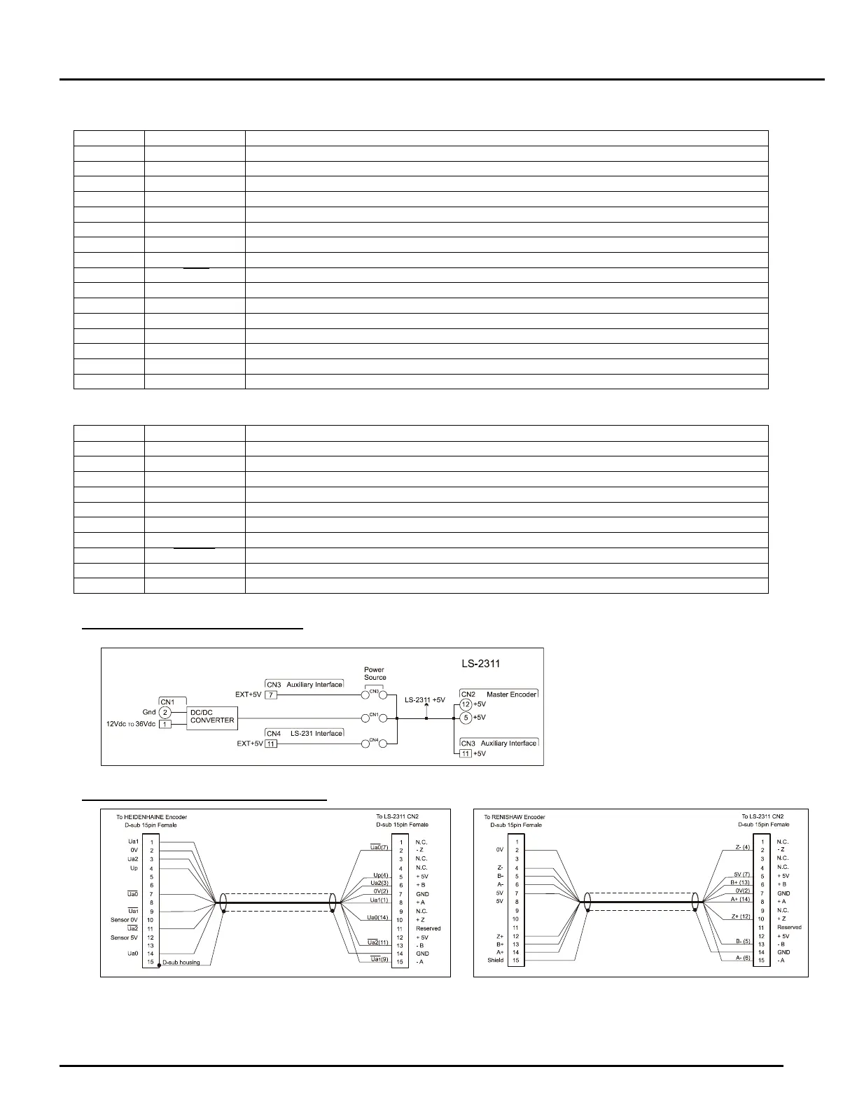
LS-2311 Power Supply Source
LS-231SE Master Encoder Cables