Operation Manual
46
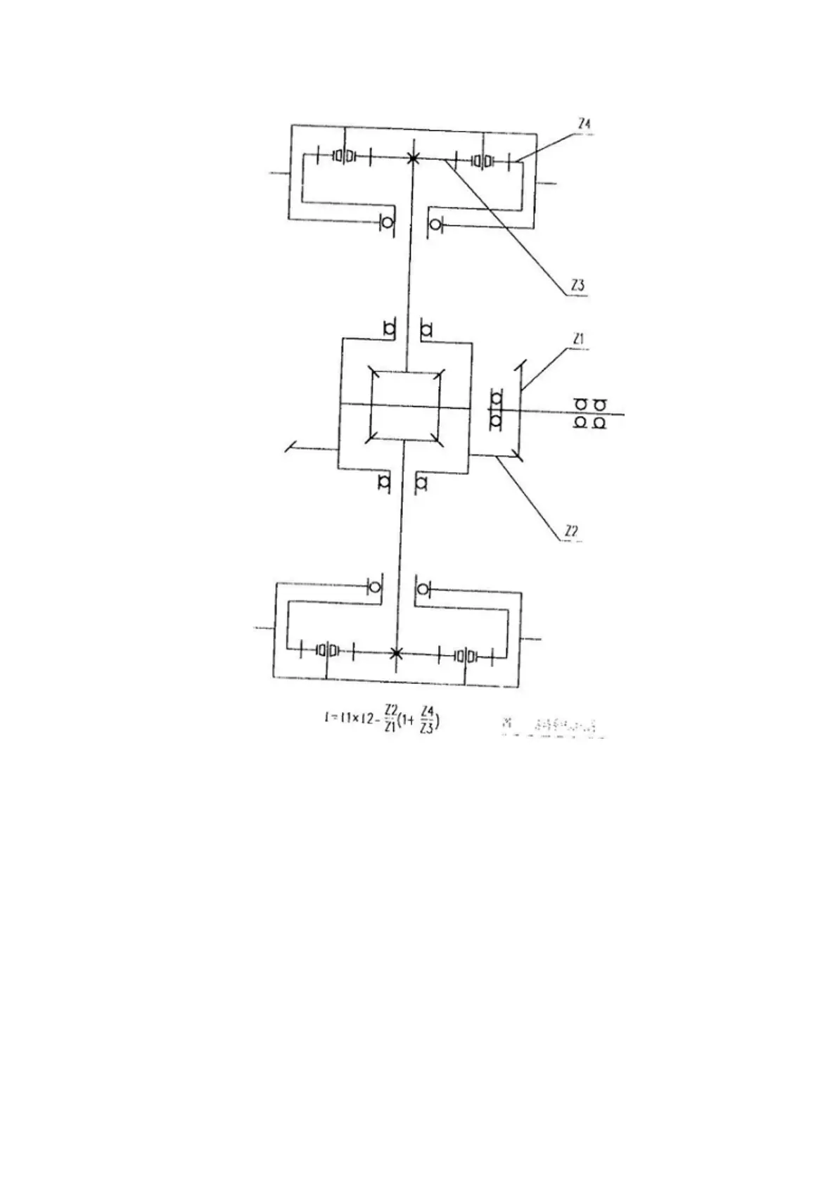
Fig. 3-4 Schematic Diagram of Working Principle of Axle
The main engine torque is transmitted from drive axle input flange through transmission shaft. After
reduction by main reducer, it changes the rotation direction to drive the driven spiral bevel gear and
differential housing to rotate. The differential housing transmits the power to the axle shaft gear by
driving cross axle and planetary gear, and then the axle shaft gear partly transmits the power to
wheel-side reducer on both sides through the axle shaft and finally to plane tary carrier after reduction
by wheel-side planetary gear to drive the wheels forward. The transmission line is as follows:
Main engine torque——Input flange——Main reducer——Differential——Axle shaft——Wheel-side
reducer——Wheel.
(iii) Requirements on checking and commissioning items in the process of use
1. The meshing clearance of spiral bevel gear pair is 0.2 ~0.3mm, and the contact impression in
tooth length and height directions shall be greater than 60% and the contact impression shall be
centered in the tooth. It will tilt to small end at no-lo ad, and the clearance and contact impression shall