CDM816D WHEEL LOADER
57
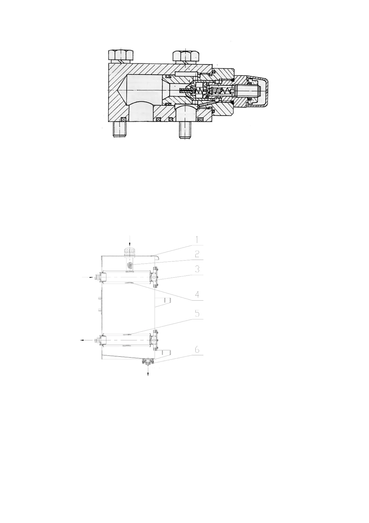
Fig.3-17 Interior Structure of Overload Filling Valve
8. The oil tank (see Fig. 3-18), with a capacity of 80L, is shared between the working device and
steering system. Air filter used to refuel is on the t op, two joints used to fit hydraulic system inlet/return
pipe are located in the left, and two oil filters are fitted to the inside to remove impurities in t he oil. To
clean oil filters periodically, it only needs to remove 6 bolts on right flange cover to remove the cover
and to pull out oil filter. Drain plug on the bottom of oil tank is used for periodic oil-replacing and
cleaning.Replace oilonce per year (2400h) at least
Fig. 3-18 Hydraulic Oil Tank
1. Hydraulic oil tank body 2. Air filter 3. Flange cover 4. Oil return filter
5. Oil suction filter 6. Plug
VII. Implement&frame
(i) Implement
The working device for the loader is mainly composed of bucket, pull rod, boom and rocker arm. See
Fig. 3-19. The tilt mechanism for the loader is provided with a single rocker arm and single pull rod and
Fill oil
Oil return
Oil outlet
Drain oil