CDM816D WHEEL LOADER
61
A
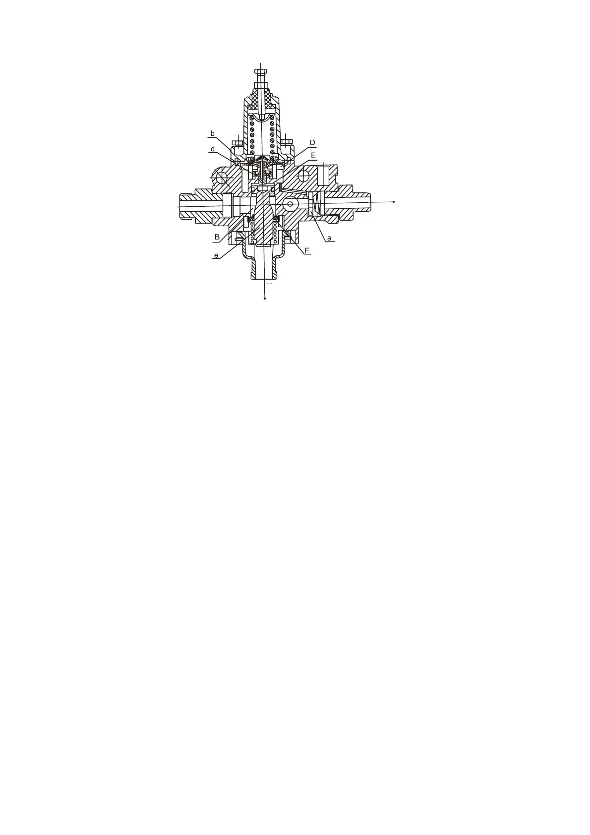
Fig. 3-22
a. One-way valve b. Diaphragm d. Pressure regulating valve assembly e. Exhaust valve stem f. Exhaust valve
Working principle: As shown in Fig. 3-22, the compressed air from air compressor flows into chamber
(B) through air inlet (A) and then to air outlet (C) through one-way valve (a) to charge the air reservoir.
When the pressure in air reservoir reaches 0.748MPa, the air in chamber (D) pushes diaphragm (b) to
open the pressure regulating valve assembly (d). Then, the air flows into chamber (E) and push the air
discharge valve rod (e) down to open the air discharge valve (f). The compressed air in chamber (B),
together with the water and impurities accumulated at the bottom of chamber (B) is discharged into
atmosphere through air outlet (F) to make the air compressor operate with no load. If the pressure in
air reservoir drops, the pressure regulating valve assembly (d) and air discharge valve (f) will be
closed in turn and the relief valve continues to supply air to the air reservoir.
After service, the relief valve, air inlet and air outlet shall be installed correctly. The adjusting screw on
the assembly has been adjusted properly before machine delivery and the user shall not adjust or
remove it without permission.
C. Air brake master valve
Air discharge port F
Air outlet C