page 22
Pc-Board DRV07 / DRV17
The pc-board DRV07 is the primary driver board of the MicorMIG 500.
Since week18 2017 the DRV07 was replaced by the DRV17. For details see page 27.
Functions
- primary driving of the transformer
- capture primary input current
- measuring temperatures
- generating internal supply voltages
- driving fans
- switching power-up relays
- PE monitoring
- coding power unit
- monitoring mains voltage
- monitoring bus voltage
LEDs
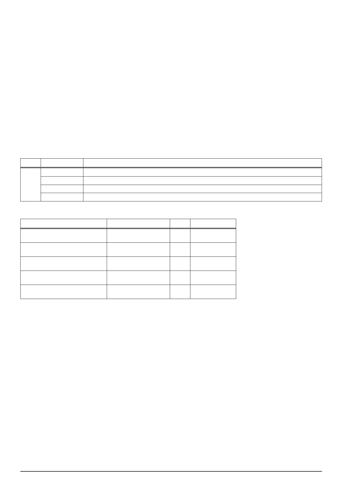
LED state designation
1 (red) blinking (1 Hz) normal operation
blinking (3 Hz) when switching o the machine (no mains voltage present)
lit weak DSP not programmed
o 3.3V supply voltage is missing
Measuring points
designation measuring point result
bus voltage
(from rectier)
X21
X24
+Uz
-Uz
ca. +580 V DC
supply voltage +24V X6-2, X7-2, X11-2, X8-2
X6-1, X7-1, X11-1, X8-1
+
-
+24V DC
supply voltage +16V X2-1
X2-2
+
-
+16V DC
supply voltage +16V (primary) X14-2
X24
+
-Uz
+16V DC
supply voltage +60V X1-5
X1-6
+
-
+60V DC