EasyManuals Logo

LORCH MicorMIG Series User Manual

LORCH MicorMIG Series
68 pages
To Next Page IconTo Next Page
To Previous Page IconTo Previous Page
Page #28 background imageLoading...
Page #28 background image
page 28
Pc-Board DC01
The pc-board DC01 is the secondary board for wiring the secondary diodes at the MicorMIG 300 and 350.
Functions
- wiring secondary diodes
- connecting resonance capacitors
- providing output voltage for measuring
Measuring points
designation measuring
point
result
output voltage X2-5
X2-1
+
-
+80V DC*
*only at machines with no VRD, at machines with activated VRD, the VRD voltage is measured.
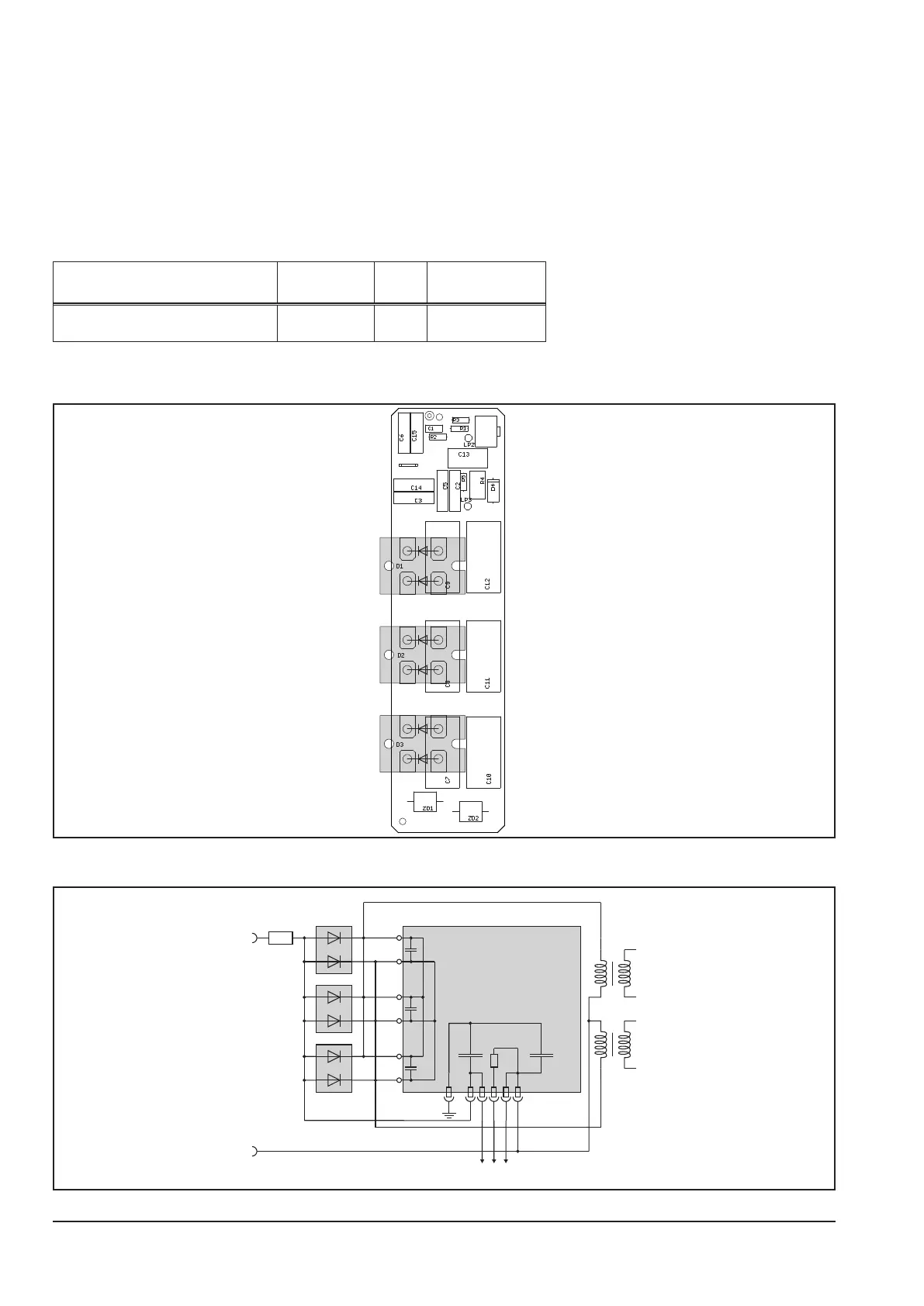
Picture pc-board DC01
X1
X2
Schematic
Rshunt
X2
2 14 35
MAPRO
X1

Questions and Answers:

Question and Answer IconNeed help?

Do you have a question about the LORCH MicorMIG Series and is the answer not in the manual?

LORCH MicorMIG Series Specifications

General IconGeneral
BrandLORCH
ModelMicorMIG Series
CategoryWelding System
LanguageEnglish

Related product manuals