page 52
Monitoring and driving the wire feed motor
The wire feed motor is driven and monitored by the pc-board DMR-RT3. If the current consumption of the motor is
too high, the machine stops with the error code E08 “Motor overcurrent”.
Motor identication
The pc-board DMR-RT3 is also used in other machines with other motors, not only at the MicorMIG. Because
of this, a identication (cable-bridge at connector X13, pins 5 and 11) is needed to indicate that the DMR-RT3 is
used in a MicorMIG machine. This cable must always be present at every MicorMIG machine.
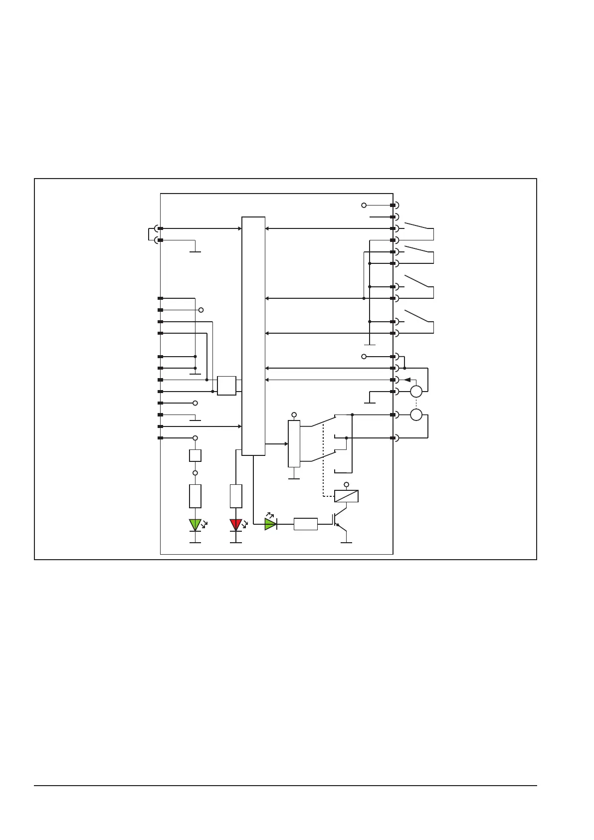
Schematic
M
G
+24V
DRV
+60V
µP
X11
X10
+5V
X5-1
X5-4
X5-2
X5-3
Tacho-ON
Tacho-Signal
LED3
X8-1
X8-2
X8-3
X8-4
X8-5
X8-6
X8-7
X8-8
CAN
+60V
+24V
+5V
LED2 LED1
DMR-RT3
X20-1
X20-2
X20-3
X20-4
+24V
X1-1
X1-2
X4-1
X4-2
X9-4
X9-3
X9-6
X9-5
X9-2
X9-1
+24V
X13-5
X13-11
RE1
identification
MicorMIG
torch
trigger
wire
inching
wire
inching
wire
retract