page 53
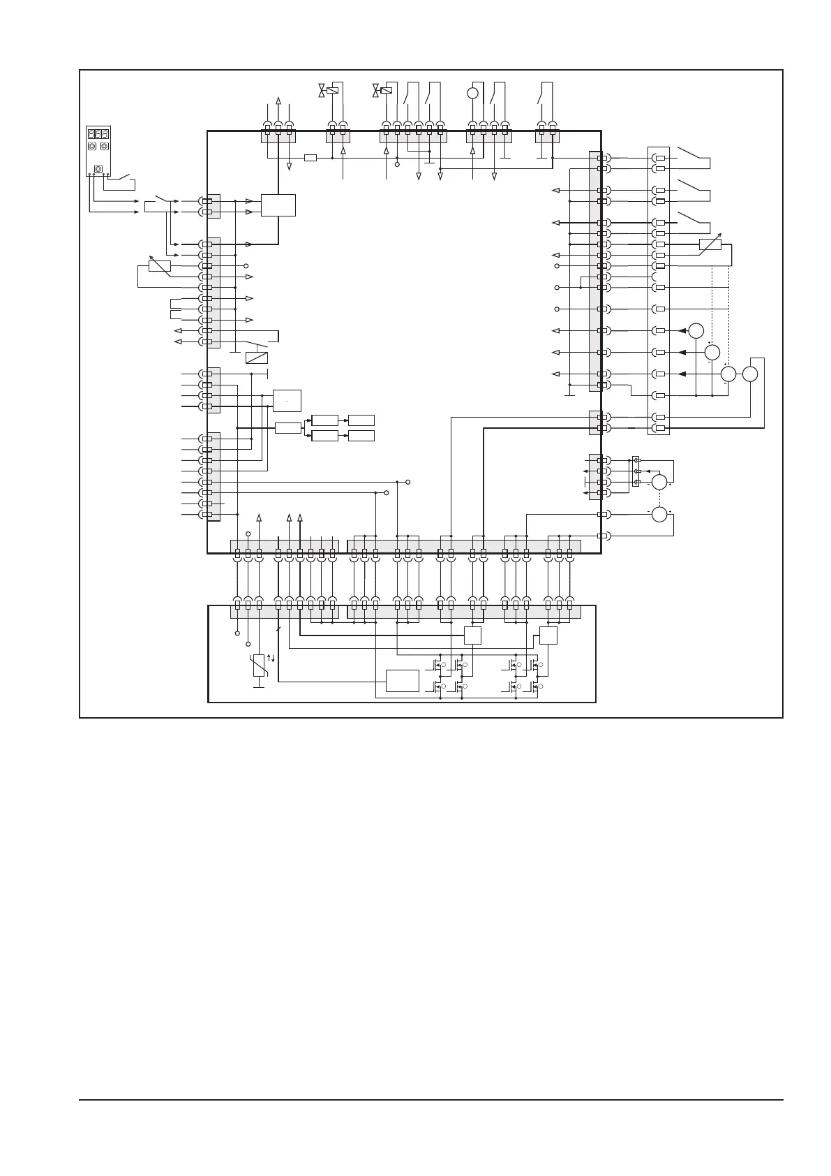
Schematic DMRPP05
I
mon.
I
mon.
8
7
6
5
4
3
2
1
+5V
+24V
12 3 4-11 12 13 16 1415
ϑ
FET
Control
X2
1 2 324 25 26
X1
6 7 8 11 12 1316 17 20 21
DMRPP-P
8
X15 X14
M
X11
X10
G
XT1
XT3
XT4
+5V
gnd
tach_in
tach_on
M
16
Amphenol 17+PE
10
2
6
4
12
5
14
7
PE
17
+24V
+5V
+12V
PushPull
X17
X5
G
G
G
11
15
9
1
digital1
digital2
analog
13
3
8
12 3 4-11 12 13 16 1415 1 2 324 25 26 6 7 8 11 12 1316 17 20 21
+70V
gnd
+5V
+24V
CAN
bus
+12V
X8
X20
X13
data
gnd
X18
+3.3V
+10V
+10V
analog in
ext.
2T
X4
X1
2
X9 X16
+24V
CAN high
CAN low
+70V mot.
gnd mot.
gnd
CAN high
CAN low
+24V
gnd
1
2
1
4
3
6
5
8
7
10
9
2
1
4
3
2
1
4
3
6
5
8
7
21 4321 43 65 21
+12V
+24V
+5V
10
11
12
13
14
16
7
8
15
3
4
9
6
5
1
2
1
2
1
2
3
4
+24V
M
X6
21
X12
21 3
DMRPP-C
+5V
temp.
Koffer aktiv Vorschub Motor
Kollisionsschutz
Gastest
Drahteinlauf
Kollisionsschutz
Gastest
Draht-
einlauf
LüferDraht-
rückzug
Drahtende-
Sensor
Ausblaß-
ventil
Gas-
ventil
Kaltdraht-
Sensor
Brenner-
interface
analog Eingang
Strom
PushPull
motor
Strom
Vorschub-
motor
Schweiß-
potential
In case of a installed Push-Pull option, instead of the DMR-RT3 the pc-board DMRPP05 is present. An additional
menu item is available where the Push-Pull torch type can be selected. The normale wire feed motor as well as
the Push-Pull motor is controlled by the DMRPP05.