page 65
Error codes
As soon as the machine is detecting a malfunction, the power unit is stopped immediately (welding process is in-
terrupted) and the corresponding error code is displayed at the front panel. Every recognized error code together
with the actual operation hour counter is written into the list of last error messages (error memory). A maximum of
16 error codes can be saved.
Using a computer with CAN interface and LorchNet Connect adapter, the error memory can be read out via the
program “Lorch System Manager”.
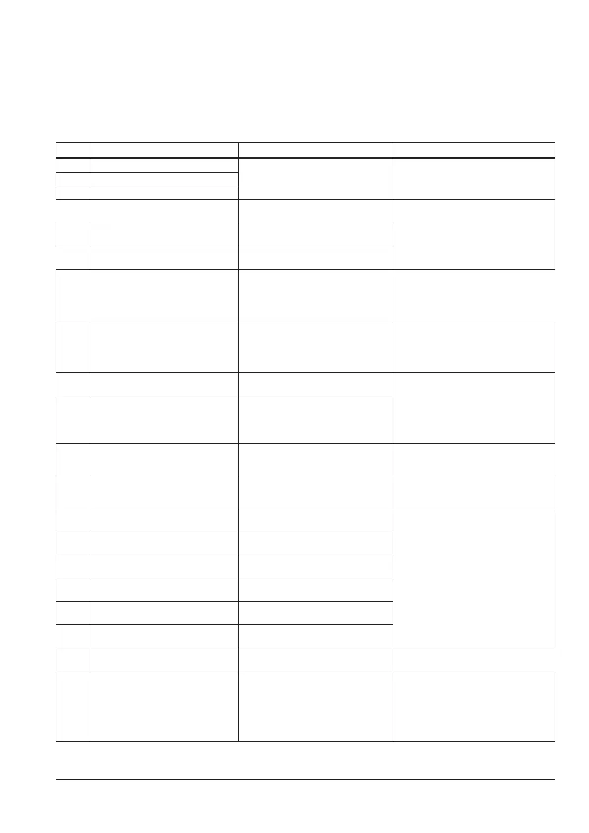
Code designation cause remarks
E01-01 Overtemperature diodes The maximum temperature was ex-
ceeded.
fans keep running to cool down the ma-
chine
for details see page 46
E01-02 Overtemperature primary modules
E01-04 Overtemperature middle heatsink temp.
E02-02 Overvoltage startup The DRV measured a too high bus volt-
age during startup.
- check mains and bus voltage
- check wiring between DRV and MAPRO
- check at ribbon cable between DRV and
MAPRO
for details see page 48
E02-04 Overvoltage primary The DRV measured a too high bus volt-
age during operation.
E02-05 Overvoltage FPGA The FPGA on the MAPRO measured a
too high bus voltage.
E04-01 PE-monitoring A current >15A was owing via the PE
wire of the mains cable.
- check machine for short circuits to the
housing
- check wiring of the reed contact at con-
nector X15 of the DRV
for details see page 49
E05-00 Cooling unit A ow of the cooling liquid could not be
detected.
- check coolant and cooling unit
- check fuses on pc-board SF 18/23/24/27
- check step-down transformer 400V/230V
- check wiring of pump and sensor
for details see page 49 and page 45
E06-00 Overvoltage secondary The DSP of the MAPRO measured a too
high output voltage (>100V).
- check wiring of the power unit to pc-board
DC0x (X2)
- check wiring between MAPRO (X5) and
DC0x (X2)
- check at ribbon cable between DRV and
MAPRO
for details see page 50
E06-01 Overvoltage secondary FPGA The FPGA of the MAPRO measured a
too high output voltage (>100V).
E07-01 EEPROM initialisation error Error during reading of the error memory,
accessing the EEPROM memory is not
possible (hardware failure).
Switch machine o and on again. At a
permanent fault, the MAPRO needs to
be exchanged.
E08-00 Wire feed The wire feed motor draws too much
current.
- check motor and its wiring
- check wiring of the DMR
for detail see page 51
E08-01 Motor overvoltage The voltage at the motor is too high
(>100V).
- check motor and its wiring
- check DMRPP05 and its wiring
for details see page 53
E08-02 Motor supply The supply voltage of the motor (60V DC)
is too high (>75V).
E08-03 Motor overcurrent 1 The wire feed motor draws too much cur-
rent (>12A).
E08-04 Motor overcurrent 2 The Push-Pull motor draws too much
current.
E08-05 Tachometer motor 1 The tacho encoder of the wire feed motor
is not connected or faulty.
E08-06 Tachometer motor 2 The tacho encoder of the Push-Pull mo-
tor or NanoFeeder is not working.
E08-10 Torch connection At the torch trigger wires a voltage > 2.5V
was measured.
check torch trigger wires for short circuits to
other wires
E12-00 Power unit startup When testing the power unit during ini-
tialisation (switching on the machine) no
output voltage could be measured.
- check wiring of the power unit to pc-board
DC0x (X2)
- check wiring between MAPRO (X5) and
DC0x (X2)
- check at ribbon cable between DRV and
MAPRO
for details see page 50
 Loading...