page 8
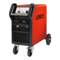
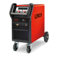
Front panel MicorMIG Feeder Panel
A2 A14
Schematic
BF
µP
CAN
UART
+
1
10
2
3
6
7
5
1
10
2
3
6
7
5
MAPRO
X2
+16V
µP
CAN
13 13
9
9
+24V
1
10
2
3
6
7
5
DMR-RT3
µP
CAN
9
X3
At compact machines the front panel is directly connected to the MAPRO. At a wire feeder MF08 the front panel is
connected to the DMR-RT3. All front panels are designed for a supply voltage range of 15V to 24V DC.
The data communication is done via CAN-bus only (pins 2 and 3 of the at ribbon cable). The serial interface
wires (UART on pins 6 and 7) are only used for programming the microprocessor (front panel software update).
 Loading...
