I336 GB I 05 13 31100162
33
G
B
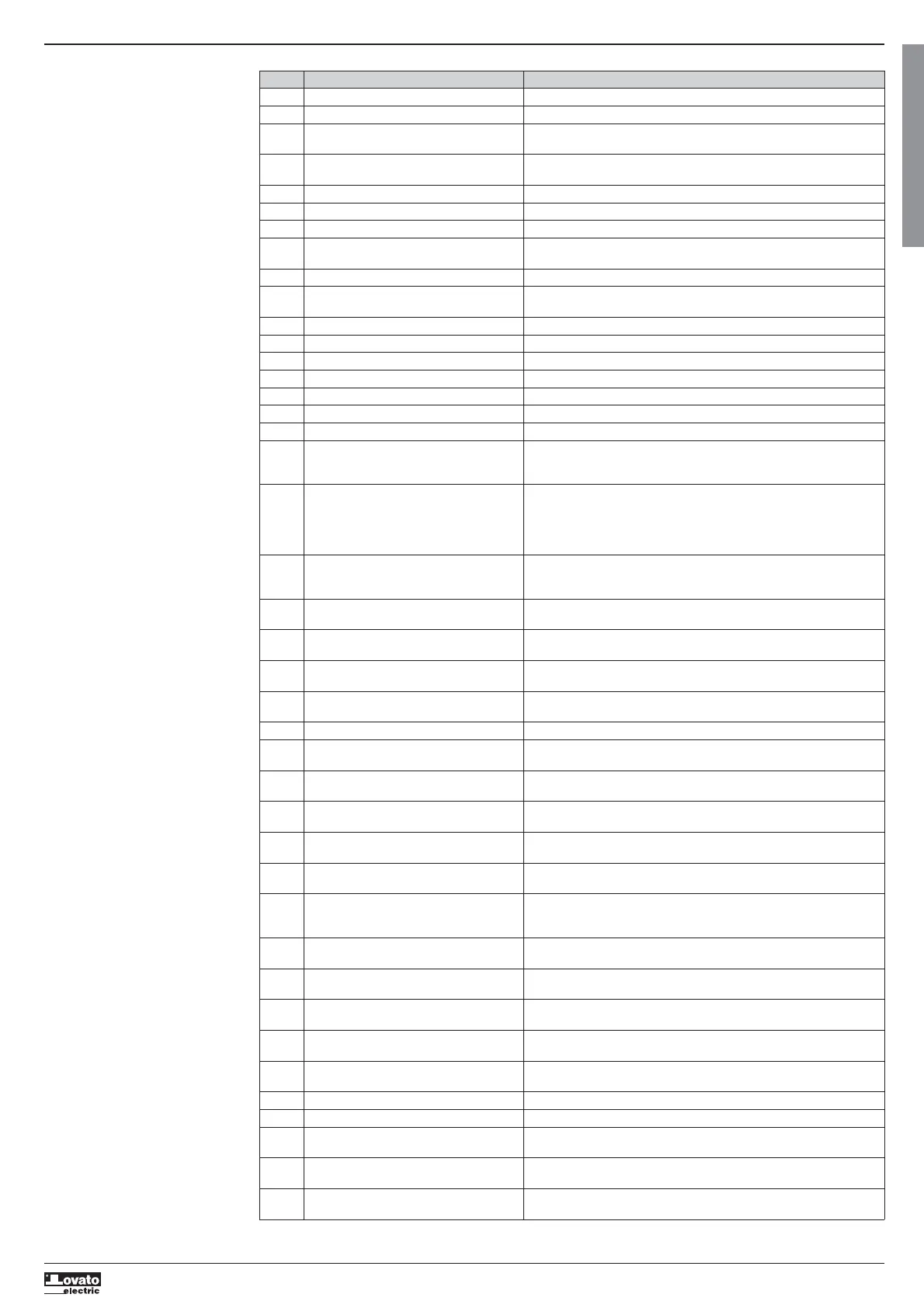
ALARM DESCRIPTION
CODE DESCRIPTION ALARM EXPLANATION
A01 Engine temperature prealarm (analog sensor) Engine temperature higher than prealarm threshold set in P09.06.
A02 High engine temperature (analog sensor) Engine temperature higher than alarm threshold set in P09.07.
A03 Analog temperature sensor fault Open circuit (disconnected) resistive temperature sensor. If the measurement has been
sent by the CAN, the alarm is generated by a specific diagnostics message.
A04 High engine temperature (digital sensor) Engine overtemperature signal on activation of digital input programmed with relevant
function.
A05 Low engine temperature (analog sensor) Engine temperature lower than alarm threshold set in P09.08.
A06 Oil pressure prealarm (analog sensor) Engine oil pressure lower than prealarm threshold set in P08.06.
A07 Low oil pressure (analog sensor) Engine oil pressure lower than alarm threshold set in P08.07.
A08 Analog pressure sensor fault Open circuit (disconnected) resistive pressure sensor. If the measurement has been sent
by the CAN, the alarm is generated by a specific diagnostics message.
A09 Low oil pressure (digital sensor) Low oil pressure signal on activation of digital input programmed with relevant function.
A10 Digital pressure sensor fault Engine stopped for over one minute, but oil sensor failed to close on no pressure signal.
Presumed break in connection.
A11 Fuel level prealarm (analog sensor) Fuel level lower than prealarm threshold set in P10.07.
A12 Fuel level low (analog sensor) Fuel level lower than alarm threshold set in P10.08.
A13 Analog level sensor fault Open circuit (disconnected) resistive fuel level sensor.
A14 Fuel level low (digital sensor) Low fuel level signal on activation of digital input programmed with relevant function.
A15 High battery voltage. Battery voltage higher than threshold set in P05.02 for time greater than P05.04.
A16 Low battery voltage Battery voltage lower than threshold set in P05.03 for time greater than P05.04.
A17 Inefficient battery Starting attempts expired with battery voltage below min. starting threshold.
A18 Battery alternator fault This alarm is generated when the engine is running (voltage and/or frequency from
generator or ‘Pick-up/W’) but the battery-charger alternator signal (D+) remains below
engine running voltage threshold P11.01 for more than 4 seconds.
A19 “Pick-up/W” signal fault With speed measurement enabled, This alarm is generated when the engine is running
(battery charger alternator signal present or voltage and/or frequency from generator)
but the ‘Pick-up/W’ speed signal has not been detected within 5 seconds. If the
measurement has been sent by the CAN, the alarm is generated by a specific diagnostics
message.
A20 “Pick-up/W” engine speed low This alarm is generated when the engine is running (battery charger alternator signal
present or voltage and/or frequency from generator) but the ‘Pick-up/W’ speed signal
remains below threshold P07.05 for longer than the time set in P07.06.
A21 “Pick-up/W” engine speed high This alarm is generated when the ‘Pick-up/W’ speed signal remains below threshold
P07.03 for longer than the time set in P07.04.
A22 Starting failed This alarm is generated after the set number of starting attempts if the engine hasn't
started.
A23 Emergency stopping This alarm is generated when terminal +COM1 is disconnected (with P23.03 enabled) or
by the opening of a digital input programmed with the ‘Emergency stop" function’.
A24 Unexpected stop This alarm is generated when the engine stops on its own after the alarms activation time
if it was not stopped by the system.
A25 No stop Alarm generated if the engine still has not stopped 65 seconds after the stop phase began.
A26 Low generator frequency This alarm is generated when the engine is running but the generator frequency is lower
than P14.11 for the time set in P14.12.
A27 High generator frequency This alarm is generated when the generator frequency is higher than P14.09 for the time
set in P14.10.
A28 Low generator voltage This alarm is generated when the engine is running but the generator voltage is lower than
P14.01 for the time set in P14.14
A29 High generator voltage This alarm is generated when the generator voltage is higher than P14.13 for the time set
in P14.15.
A30 Generator voltages asymmetry Alarm generated when the imbalance between the generator voltages exceeds P14.07 for
the time set in P14.08.
A31 Max. generator current The generator current exceeds the percentage threshold set in P15.01 for the delay set in
P15.02. When this alarm is generated, you must wait for the time set in P15.05 before
resetting it.
A32 Generator short-circuit The generator current exceeds the percentage threshold set in P15.03 for the delay set in
P15.04.
A33 Generator overload Electronic cutout tripped because of percentage current and protection curve selected.
When this alarm is generated, you must wait for the time set in P15.07 before resetting it.
A34 Generator external protection intervention If programmed, this alarm is generated when the contact of the digital input of the
generator thermal cutout closes, if the genset is running.
A35 Generator kW threshold exceeded The generator active power exceeds the percentage threshold set in P22.18 for the delay
set in P22.19.
A36 Generator earth fault The earth leakage current of the generator has exceeded the threshold set as an absolute
value in P15.08 for the delay set in P15.09.
A37 Generator phase sequence error The generator phase sequence does not correspond to the programmed sequence.
A38 Mains phase sequence error The mains phase sequence does not correspond to the programmed sequence.
A39 System frequency settings error Alarm generated when the system frequency does not correspond to the set rated
frequency.
A40 Generator contactor anomaly Alarm generated if a discrepancy is detected after the set time between the sate of the
command output and the generator contactor/circuit breaker feedback input.
A41 Mains contactor anomaly Alarm generated if a discrepancy is detected after the set time between the sate of the
command output and the mains contactor/circuit breaker feedback input.
 Loading...