Getting started
CG-6 Operation Manual p/n 115370001 Rev A
Overview of the console and keypad
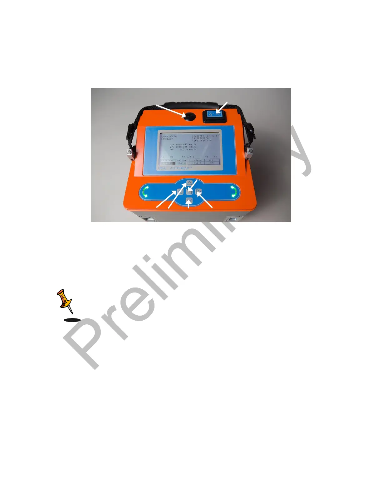
The following picture shows the front panel of the instrument. It is comprised of a display
for viewing menus and results; keypad for entering parameters and recording data.
Figure 2-7 The CG-6 Autograv
TM
Console and Keypad
The leveling arrows indicate the direction to turn the tripod leveling screws. The left-hand
side arrow refers to the left-hand leveling screw and right-hand side arrow refers to the
right-hand leveling screw. The right hand screw adjusts X and Y levels simultaneously.
Note: You will level the CG-6 Autograv
TM
by adjusting the right-hand
screw first, then the left-hand screw.
You can navigate between the menus located at the bottom of the screen by using the
up, down, left and right arrows. In any screen, move the cursor either to BACK or
CANCEL and press the Enter button to go back to the previous screen.
Starting up the CG-6 Autograv
TM
When starting-up the CG-6 Autograv
TM
for the first time, or after it has been turned off
for more than 24 hours, requires the following steps and waiting periods.
Powering up the CG-6 Autograv
TM
. Please refer to the section entitled: Powering up
the CG-6 Autograv
TM
below
Left, up, down and
right Arrows
Left-hand
side leveling
screw
Right-hand
side leveling
screw
External GPS
Mounting Point
 Loading...