Chapter 9. Installation and Wiring
9-5
(4) Mount the wire duct as it is needed.
If the clearances are less than those in Fig below, follow the instructions shown below
•
If the wire duct is mounted on the upper part of the PLC, make the wiring duct clearance 50 ㎜ or less for good
ventilation. Also, allow the distance enough to press the hook in the upper part from the upper part of the PLC.
•
If the wire duct is mounted on the lower part of the PLC, make optic or coaxial cables contact it and consider the
minimum diameter of the cable.
(5) To protect the PLC from radiating noise or heat, allow 100 ㎜ or more clearances between it and parts. Left or right
clearance and clearance from other device in the left or right side should be 100 ㎜ or more.
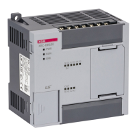
(6) GM7U has hooks for DIN rail (width 3.5 mm) in the base unit and expansion modules.
High voltage
device
Other
device
100mm or more
Heat generating device
80mm or more
80mm
or more
DIN rail
K7M-DR30U

 Loading...


