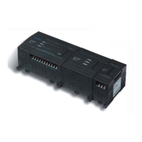
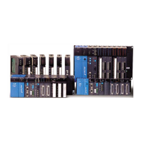
Do you have a question about the LS Industrial Systems XBC-E Series and is the answer not in the manual?
Explains how to use the manual, covering specifications, functions, and handling instructions for the XGB series PLC.
Details the key features of the XGB system, including hardware performance, compact size, improved programming, and optimized communication.
Outlines the system configuration for the XGB E-Type PLC, detailing total I/O points, expansion modules, and main unit models.
Lists the available products, including main units, power supplies, option modules, and cables, with their respective specifications.
Provides definitions for terms used throughout the manual, such as Module, Unit, PLC System, XG5000, I/O image area, Cnet, FEnet, Pnet, Dnet, RTC, and Watchdog Timer.
Provides a basic setup and programming guide for the XGB PLC, outlining necessary items and software installation.
Details the installation process for the XG5000 software, a crucial tool for programming the XGB PLC.
Guides users through creating a new project, writing a ladder logic program, and simulating it without a physical PLC.
Covers the essential steps for installing and wiring the PLC, including power wiring and connecting to a computer.
Explains how to transfer the written program to the PLC using XG5000, including connection settings and writing procedures.
Crucial safety guidelines for designing PLC systems, installation, wiring, and disposal to prevent hazards and ensure safe operation.
Details the power budget, including internal DC5V power calculation and specifications for power supply of the main unit.
Identifies and explains the function of various parts of the "E" type XGB PLC, such as indicator LEDs, communication ports, and switches.
Provides dimensional drawings for different XGB models, useful for panel design and installation planning.
Explains the procedures for installing the PLC module, including mounting on a DIN rail and direct panel installation using screws.
Offers essential guidelines for wiring, including disconnecting power, using terminal covers, proper grounding, and avoiding foreign materials.
Lists general specifications for the XGB compact type CPU, covering environmental conditions, vibration, shock, and noise resistance.
Details the performance specifications of XGB compact type CPUs, including program control, I/O control, language, processing speed, and data areas.
Explains the data backup time for the main unit when the RTC module is not installed, relying on a super capacitor.
Describes program execution methods, including cyclic operation, interrupt operation, and constant scan, along with operation processing during momentary power failure.
Explains the two types of memory in the CPU module: Program Memory and Data Memory, detailing their functions and areas.
Covers various data types, including bit data, nibble/byte data, word data, double word data, and real data, with their application methods.
Illustrates the configuration diagram of data memory, showing bit and word data areas, and the user program area.
Explains the concept of a program and its classification, including initializing programs, scan programs, cycle time interrupt programs, and external interrupt programs.
Describes the three operation modes of the CPU module: RUN, STOP, and DEBUG, detailing their operation processing and change methods.
Provides a comprehensive classification of instructions, categorized into Basic Instructions and Application Instructions, with their details and remarks.
Details basic instructions such as Contact Point, Union, Reverse, Master Control, Output, Sequence/Last-input preferred, End, and Non-process instructions.
Covers various application instructions including Data Transfer, Conversion, Data Type Conversion, Output Terminal Compare, and Increase/Decrease instructions.
Explains instructions for controlling the F area, specifically FSET, FRST, and FWRITE operations.
Explains bit control instructions used in word areas, specifically focusing on Bit of Word (B) and Inverse Bit of Word (BN).
Outlines special and communication instructions, including common instructions for special modules like GET and PUT.
Provides a detailed list of special relay (F) bits, classifying them by word area and describing their functions and contents.
Explains how to interpret the instruction details tables, covering mnemonic name, area available, step count, flags, ladder rung examples, and operand settings.
Details the specifications of the XGB series' built-in high-speed counter, including performance, counter input, and output specifications.
Explains the internal memory structure for the high-speed counter, focusing on special areas for parameter and operation command usage.
Provides practical examples of how to set up and use the high-speed counter parameters, including monitoring and testing.
Classifies and lists the types of available option modules, such as DC input, TR output, Analog I/O, RTC, and Memory modules.
Provides specifications for the RTC battery, including voltage, warranty, purpose, and important notices for usage and life.
Explains how to use the RTC function, covering reading/setting clock data, modifying clock data by program, and expressing the day.
Details the specifications for the XGB DC input option board, including input points, insulation method, voltage, current, and response time.
Outlines the performance and input specifications for the XGB high-speed counter, covering signal types, count modes, and voltage/current requirements.
Describes the internal memory usage for high-speed counters, focusing on U device for parameter and operation command areas, and auto-registration.
Provides an example of setting up and monitoring a high-speed counter using a DC input board, illustrating parameter settings and monitoring.
Details the specifications for the transistor output option board, including output points, insulation method, voltage, current, and response time.
Explains the specifications, structure, and usage of the memory module, including saving and opening programs, and handling password protection.
Compares MASTER-K devices and functions with XGB, detailing symbol, device, and function mappings for compatibility.
Guides on performing periodic maintenance and inspections to ensure equipment reliability, covering control and ambient operating environments.
Provides methods for diagnosing and troubleshooting PLC system faults, including error logs, fault types, and operational errors.
Offers initial troubleshooting steps, including visual checks, power verification, mode cycling, and area narrowing down.
Explains common troubles with input and output circuits and provides corrective actions, including diagrams for reference.
Lists common error codes, their causes, recommended actions, operation status, LED status, and diagnosis points for troubleshooting.
Details how to diagnose system and network status using XG-PD, covering CPU module information, communication module information, frame monitor, and status by service.
Provides troubleshooting steps for common errors such as P2P parameter setting errors, communication failures, and response frame misses.
Explains how to diagnose faults in external devices using system flags and troubleshooting steps for detected errors and warnings.
Describes the Force I/O function for simulating processes and forcing physical I/O states, including cautions for usage.
Explains the Clear All PLC function, which resets the PLC to its default "out-of-box" state, including program, parameter, and password deletion.
Explains how numbers (data) are expressed in decimal, binary, hexadecimal, and binary coded decimal systems, and how they are processed in the PLC.
Details the expression of integer numbers in signed operations, explaining the role of the sign bit in 16-bit and 32-bit systems.
Provides supplementary information regarding timer operations and timing charts, illustrating how timers function with different conditions and inputs.
Outlines the requirements for conforming to the EMC Directive, covering electromagnetic emissions and immunity standards, and control panel guidelines.
Details the requirements for conforming to the Low-voltage Directive, focusing on power supply modules, I/O modules, and special/communication modules.
| Brand | LS Industrial Systems |
|---|---|
| Model | XBC-E Series |
| Category | Controller |
| Language | English |


