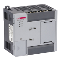
Do you have a question about the LS Industrial Systems XBC-DR10E and is the answer not in the manual?
Details the system configuration of the XGB E-Type series, including total I/O points, maximum expansion modules, and main unit types.
Guides on creating a new project, writing a ladder logic program, and simulating the program without a physical PLC.
Details on connecting power and I/O wiring to the PLC according to the provided drawing.
Steps for transferring the written program to the PLC, including connection settings and the writing process.
Provides critical safety warnings and precautions for designing PLC systems, installing modules, and handling the product.
Describes the procedures and precautions for mounting the XGB PLC module, including DIN rail installation and panel mounting.
Offers general guidelines for wiring, including safety precautions, terminal torque, power supply specifications, and I/O device wiring concepts.
Explains the communication specifications, including built-in serial communication interface (Cnet) and communication ports (Port 1, Port 2).
Details the performance specifications for the XGB compact type CPU, covering program control, I/O control, language, processing speed, and data area.
Describes the operation processing of each mode: RUN mode, STOP mode, and DEBUG mode.
Explains the Watchdog Timer (WDT) function for detecting program delays caused by hardware or software errors.
Details the specifications of the XGB series High-speed counter, including performance and input specifications.
Explains the functions of the 'E' type high-speed counter, including counter modes, input modes, and auxiliary modes.
Provides examples of using the high-speed counter, including setting parameters and monitoring.
Details the specifications for the built-in High Speed Counter module, including performance and counter input specifications.
Provides examples of using the DC input board high-speed counter, including setup and monitoring.
Explains the memory module, its specifications, structure, and how to use it for saving or loading programs.
Provides a detailed compatibility table between MASTER-K and XGB devices, focusing on special relays.
Outlines preventive and predictive maintenance practices, including checks on operating environment and equipment integrity.
Guides on diagnosing system issues, including error and warning logs, and general troubleshooting steps.
Provides examples of common input and output circuit troubles and their corresponding corrective actions.
Lists all error codes, their causes, recommended actions, operation status, LED status, and diagnosis points.
Explains how to check system and network status using XG-PD, including CPU module information and communication module information.
Provides troubleshooting steps for common errors such as P2P parameter setting errors, communication issues, and response frame misses.
Describes how to diagnose faults in external devices using flags and troubleshooting steps for detected errors or warnings.
Explains the Force I/O function for simulating processes during development and provides cautions for its use.
| Brand | LS Industrial Systems |
|---|---|
| Model | XBC-DR10E |
| Category | Controller |
| Language | English |


