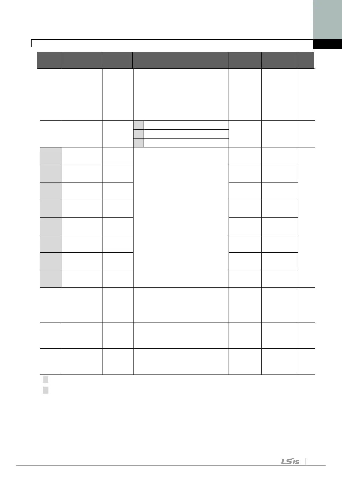
7. Function List
LED
Parameter
Min/Max
Description
Factory
Adjustable
Page
F29 [Torque
boost in
reverse
direction]
This parameter sets the
amount of torque boost
applied to a motor during
reverse run.
It is set as a percent of Max
5 X
F30 [V/F pattern] 0/2 0 {Linear} 0 X
2 {User V/F}
F31
[User V/F
0/400
This parameter is active
when F30 – [V/F pattern] is set
to 2 {User V/F}.
It cannot be set above F21
– [Max frequency].
The value of voltage is set
in percent of H70 – [Motor
rated voltage].
The values of the lower-
numbered parameters cannot
be set above those of higher-
numbered.
15.0 X
F32 [User V/F
voltage 1]
0/100
[%]
25 X
F33 [User V/F
0/400
30.0 X
F34 [User V/F
voltage 2]
0/100
[%]
50 X
F35 [User V/F
0/400
45.0 X
F36 [User V/F
voltage 3]
0/100
[%]
75 X
F37 [User V/F
0/400
60.0 X
F38 [User V/F
voltage 4]
0/100
[%]
100 X
F39 [Output
voltage
adjustment]
40/110
[%]
This parameter adjusts the
amount of output voltage.
The set value is the
percentage of input voltage.
100 X
F40 [Energy-
saving level]
0/30 [%] This parameter decreases
output voltage according to
load status.
0 0
F50 [Electronic
thermal
0/1 This parameter is activated
when the motor is overheated
0 0
2) Only displayed when F24 (Freq High/Low limit select) is set to 1.
3): Set F30 to 2 (User V/F) to display this parameter.
 Loading...